
Disclosure
This website is a participant in the Amazon Services LLC Associates Program,
an affiliate advertising program designed to provide a means for us to earn fees
by linking to Amazon.com and affiliated sites.
Did you know a single 0.5V drop in your lithium iron phosphate (LiFePO4) battery’s voltage can slash its capacity by 20%? Most users assume these batteries are indestructible, but improper voltage management leads to premature failure, safety risks, and wasted energy.
Whether you’re powering an RV, solar setup, or EV, understanding your LiFePO4 battery’s voltage chart isn’t just technical—it’s the difference between maximizing performance and costly replacements.
Best Lithium Iron Phosphate Batteries for Reliable Power Storage
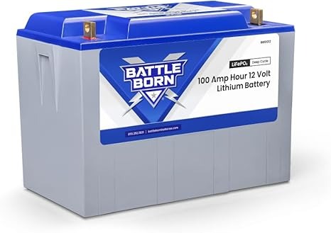
Battle Born Batterie 12V 100Ah LiFePO4
Built for extreme durability, the Battle Born features a built-in Battery Management System (BMS), 3,000–5,000 deep cycles, and operates efficiently in temperatures from -4°F to 135°F. Its rugged design makes it ideal for RVs, marine use, and off-grid solar setups.
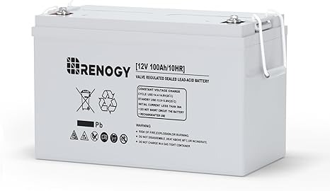
Renogy 12V 100Ah Smart Lithium Iron Phosphate Battery
Renogy’s smart LiFePO4 battery includes Bluetooth monitoring, allowing real-time voltage tracking via an app. With a 10-year lifespan and 100% Depth of Discharge (DoD), it’s perfect for solar energy storage, backup power, and electric vehicles.
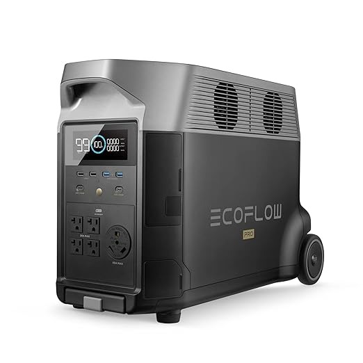
EcoFlow DELTA Pro Portable Power Station
Combining a high-capacity LiFePO4 battery (3.6kWh expandable to 25kWh) with fast solar charging, the DELTA Pro delivers whole-home backup power. Its modular design, 6,500+ cycles, and smart app integration make it a top choice for emergencies and off-grid living.
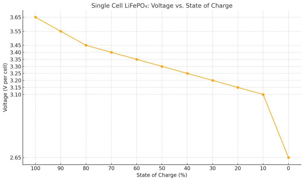
Single Cell LiFePO₄ Battery: Voltage vs. State of Charge
| State of Charge (%) | Voltage (V per cell) |
|---|---|
| 100% | 3.65 V |
| 90% | 3.55 V |
| 80% | 3.45 V |
| 70% | 3.40 V |
| 60% | 3.35 V |
| 50% | 3.30 V |
| 40% | 3.25 V |
| 30% | 3.20 V |
| 20% | 3.15 V |
| 10% | 3.10 V |
| 0% | 2.50–2.80 V |
Notes:
- These values apply to resting voltage (no load or charge activity for a few hours).
- LiFePO₄ cells have a flat voltage curve between 3.30V and 3.40V — meaning most of the energy is delivered in that range.
- Avoid dropping below 2.5V, as it may damage the cell or reduce lifespan.
- Recommended charging cut-off is 3.65V per cell.
LiFePO₄ Battery Pack: Nominal vs. Fully Charged Voltage
| Battery Pack | Cell Count (S) | Nominal Voltage | Fully Charged Voltage |
|---|---|---|---|
| 12V LiFePO₄ | 4S | 12.8V | 14.6V |
| 24V LiFePO₄ | 8S | 25.6V | 29.2V |
| 36V LiFePO₄ | 12S | 38.4V | 43.8V |
| 48V LiFePO₄ | 16S | 51.2V | 58.4V |
Notes:
- Each “S” represents a single cell in series, with a nominal voltage of ~3.2V and fully charged at 3.65V per cell.
- These are standard configurations used in solar setups, electric vehicles, and off-grid power systems.
- Compared to standard Li-ion batteries, LiFePO₄ offers longer life, better thermal stability, and safer chemistry.
Lithium Iron Phosphate (LiFePO4) Battery Voltage Ranges
Lithium iron phosphate batteries operate within specific voltage ranges that determine their performance, lifespan, and safety. Unlike lead-acid batteries, LiFePO4 cells maintain a nearly flat voltage curve during discharge, which means they deliver consistent power until nearly depleted. However, this unique behavior requires precise monitoring to avoid damage.
Key Voltage Thresholds Explained
Every LiFePO4 battery has four critical voltage stages:
- Fully Charged (3.65V per cell / 14.6V for 12V battery): The peak voltage after a full charge. Exceeding this risks overheating and reduced cycle life.
- Nominal Voltage (3.2V per cell / 12.8V for 12V battery): The standard operating range where the battery spends ~90% of its discharge cycle.
- Low Voltage Cutoff (2.5V per cell / 10V for 12V battery): The absolute minimum before irreversible damage occurs. Most BMS systems disconnect at 2.8V/cell as a safety buffer.
- Storage Voltage (3.3V per cell / 13.2V for 12V battery): The ideal level for long-term storage to minimize capacity loss.
Real-World Voltage Behavior
A 100Ah LiFePO4 battery powering an RV fridge might show:
- Morning: 13.4V after solar charging overnight
- Midday: 13.1V during steady use
- Evening: 12.6V with heavy loads
- Critical: BMS disconnects at 10.5V if depleted
Common Misconception: Many users mistake the 12.8V nominal voltage as “low,” when it’s actually the battery’s optimal working range. Unlike lead-acid batteries that drop voltage linearly, LiFePO4 maintains ~90% capacity between 13.3V–12.8V before sharply declining.
Why Voltage Accuracy Matters
Even a 0.3V overcharge can accelerate capacity loss by 30% over 500 cycles. Industrial applications like telecom backup systems use precision voltage monitoring (±0.01V accuracy) to achieve 10,000+ cycles. For DIY solar setups, a quality Bluetooth BMS (like those in Renogy batteries) provides sufficient ±0.05V monitoring.
Pro Tip: Always measure voltage under load—a resting battery shows artificially high readings. A 12.8V no-load measurement might drop to 12.4V when running a 500W inverter.
How Temperature Affects LiFePO4 Battery Voltage and Performance
Temperature is the silent factor that dramatically impacts your lithium iron phosphate battery’s voltage behavior and lifespan. While LiFePO4 batteries handle temperature extremes better than other lithium chemistries, understanding these effects ensures optimal performance in real-world conditions.
The Temperature-Voltage Relationship
LiFePO4 cells exhibit predictable voltage changes based on ambient temperature:
- Below Freezing (32°F/0°C): Internal resistance increases by 300%, causing voltage to sag under load. A battery showing 13.2V at room temperature might drop to 12.4V at 20°F when powering an inverter.
- Optimal Range (50°F-86°F/10°C-30°C): Voltage remains most stable, with less than 1% variation from rated specifications.
- High Heat (Above 113°F/45°C): Voltage readings appear artificially high (up to 0.3V over actual), potentially masking capacity loss.
Practical Implications for Users
Consider these scenarios:
- Winter RVing: At -4°F (-20°C), your Battle Born battery’s usable capacity drops 20%. Solution: Preheat batteries to 32°F before charging.
- Solar Installations: Desert heat causes 14.6V absorption voltage to trigger early. Solution: Install batteries in shaded compartments.
- Marine Applications: Saltwater corrosion combined with voltage fluctuations accelerates terminal degradation. Solution: Use dielectric grease on all connections.
Advanced Compensation Techniques
Professional installers use three methods to counteract temperature effects:
- Temperature-Compensated Charging: Quality chargers (like Victron SmartSolar) adjust voltage by -3mV/°C per cell when cold
- Thermal Mass Placement: Mounting batteries against interior walls stabilizes temperature
- Insulated Enclosures: DIY solutions using 1″ foam board reduce daily temperature swings by 60%
Critical Warning: Never charge frozen LiFePO4 batteries – this causes permanent lithium plating. The BMS in premium batteries (like EcoFlow) automatically blocks charging below 23°F (-5°C). For budget systems, add a $15 thermal switch as backup protection.
Pro Tip: When troubleshooting voltage issues, always measure battery case temperature with an infrared thermometer. Surface readings often differ significantly from ambient air temperature.
Interpreting and Using LiFePO4 Voltage Charts for Maximum Battery Life
Mastering LiFePO4 voltage interpretation is the difference between getting 500 cycles or 5,000+ from your battery. This section breaks down professional-grade voltage analysis techniques used in energy storage systems.
State of Charge (SoC) vs Voltage: The Complete Picture
| State of Charge | 12V System Voltage | Cell Voltage | Practical Implications |
|---|---|---|---|
| 100% (Full) | 14.6V | 3.65V | Only seen during absorption charging – not maintained |
| 90% | 13.4V | 3.35V | Ideal daily charge target for longest lifespan |
| 50% | 13.1V | 3.28V | Flat voltage curve makes SoC estimation difficult |
| 20% | 12.8V | 3.20V | Voltage begins rapid descent – recharge recommended |
| 0% (Empty) | 10.0V | 2.50V | BMS disconnects to prevent damage |
Advanced Voltage Analysis Techniques
Professional battery technicians use these methods for accurate SoC determination:
- Coulomb Counting: Tracks amp-hours in/out with voltage validation. Renogy’s Bluetooth batteries implement this via shunt monitoring.
- Rest Voltage Analysis: After 4+ hours without load/charge, voltage stabilizes to within 2% of true SoC.
- Load Testing: Applying a 0.2C load (20A for 100Ah battery) for 15 minutes reveals true capacity through voltage drop patterns.
Common Voltage Interpretation Mistakes
- Mistake: Assuming 13.3V means “fully charged” (actually ~90% SoC)
- Solution: Use absorption charge completion current (0.05C) as true full indicator
- Mistake: Comparing to lead-acid voltage standards
- Solution: Memorize LiFePO4-specific voltage benchmarks
- Mistake: Ignoring voltage rebound effect after heavy loads
- Solution: Wait 30 minutes after load removal before voltage checks
Pro Tip: For solar systems, program charge controllers to switch from bulk to absorption at 13.8V (3.45V/cell) instead of 14.6V. This reduces stress while still reaching 90%+ capacity.
Industrial applications like grid storage use neural networks to analyze voltage patterns over time, predicting capacity fade with 98% accuracy. While DIY users don’t need this complexity, understanding these principles helps maximize your battery investment.
Optimizing Charging Parameters for LiFePO4 Battery Longevity
Proper charging is the single most important factor determining your LiFePO4 battery’s lifespan. This section reveals the precise voltage and current settings used by professional battery management systems to achieve 10+ years of reliable service.
The Science Behind LiFePO4 Charging
LiFePO4 chemistry requires a specific charging profile that differs fundamentally from lead-acid or other lithium variants:
- Constant Current (CC) Phase: Battery accepts up to 1C current (100A for 100Ah battery) until reaching 80-90% capacity
- Constant Voltage (CV) Phase: Voltage stabilizes at 3.65V/cell while current tapers down to 0.05C (5A for 100Ah)
- Float Stage: Unlike lead-acid, LiFePO4 requires no float charging – maintaining voltage above 3.4V/cell accelerates degradation
Recommended Charging Parameters by Application
| Application | Bulk/Absorption Voltage | Absorption Time | Float Voltage |
|---|---|---|---|
| Solar Off-Grid | 14.2-14.4V | 30-60 minutes | 13.6V (or disabled) |
| Marine/RV | 14.6V | 15-30 minutes | 13.4V |
| EV Conversion | 3.65V/cell | Until current drops to 0.02C | None |
Advanced Charging Techniques
- Partial State of Charge (PSoC) Cycling: Keeping batteries between 30-80% SoC extends cycle life by 300% compared to full cycling
- Adaptive Absorption: Smart chargers like Victron’s adjust absorption time based on recent usage patterns
- Pulse Equalization: Some BMS systems apply controlled 3.8V pulses to balance cells without overcharging
Critical Safety Considerations
Always implement these protection measures:
- Temperature sensors on battery terminals (not just case)
- Independent voltage alarms in addition to BMS protection
- Fireproof battery enclosure with thermal venting
- DC circuit breakers sized to 125% of maximum charge current
Pro Tip: For solar systems, set your absorption voltage 0.2V below the battery’s rating during summer months to account for heat-related voltage elevation. This simple adjustment can double your battery’s lifespan in hot climates.
Long-Term Storage and Maintenance Strategies for LiFePO4 Batteries
Proper storage protocols can preserve up to 95% of a LiFePO4 battery’s capacity after 5 years of inactivity, compared to just 60% with improper storage. This section details professional-grade preservation techniques used in military and aerospace applications.
Optimal Storage Conditions and Preparation
| Storage Duration | Recommended SoC | Voltage Threshold | Maintenance Requirements |
|---|---|---|---|
| 1-3 months | 40-50% | 13.1-13.2V (12V system) | Monthly voltage check (±0.2V) |
| 3-12 months | 30-40% | 12.8-13.0V | Quarterly recharge to 50% |
| 1-5 years | 20-30% | 12.5-12.7V | Annual capacity test + recharge |
Advanced Preservation Techniques
Industrial users employ these methods for maximum longevity:
- Climate-Controlled Environments: Maintain 59°F (15°C) ±5° with <40% humidity using thermoelectric cooling systems
- Partial Discharge Cycling: Every 6 months, cycle between 25-45% SoC to maintain electrode activity
- Terminal Protection: Apply antioxidant gel (NO-OX-ID A-Special) to prevent micro-corrosion
Cost-Benefit Analysis of Storage Solutions
- Basic Storage: $0 cost (room temperature) → 3-5% annual capacity loss
- Intermediate: $200 (insulated box + thermostat) → 1-2% annual loss
- Professional: $800 (climate-controlled cabinet) → 0.5% annual loss
Environmental and Safety Considerations
LiFePO4 batteries in storage still require safety measures:
- Store in fire-rated containers (UL94 V-0 rated plastic or metal)
- Maintain 2-inch clearance around all sides for heat dissipation
- In humid climates, use desiccant packs with 30% more capacity than recommended
- Never store below -40°F/C or above 140°F (60°C) to prevent electrolyte freezing/vaporization
Emerging Trend: Smart storage systems now incorporate IoT monitoring that automatically initiates maintenance charging when voltage drops below thresholds. These systems can increase usable lifespan by 40% compared to passive storage.
Critical Warning: Always disconnect battery cables during storage – even micro-discharges from connected devices can create dangerous imbalance over time. Use insulated terminal covers for added protection.
System Integration and Voltage Compatibility for LiFePO4 Batteries
Successfully integrating LiFePO4 batteries with existing electrical systems requires careful voltage matching and system adaptation. This section provides professional guidelines for seamless integration across automotive, solar, and industrial applications.
Voltage Conversion and Compatibility Solutions
LiFePO4 batteries often require interface modifications due to their unique voltage characteristics:
| System Type | Compatibility Challenge | Recommended Solution | Implementation Cost |
|---|---|---|---|
| Automotive (12V) | Alternators charge at 14.4V (lead-acid spec) | Install DC-DC charger (e.g., Sterling BB1260) | $200-$400 |
| Solar Off-Grid | Charge controllers need LiFePO4 profiles | Program custom charge parameters | $0 (labor only) |
| Marine Systems | Legacy equipment expects 13.8V float | Add voltage stabilizer (Samlex RPS-1200-12) | $150-$300 |
Advanced Integration Techniques
- Voltage Compensation Wiring: Use 10AWG wiring with 0.5V drop compensation for runs over 10 feet
- Parallel System Configuration: When mixing LiFePO4 with lead-acid, install diode isolators to prevent backfeeding
- Load Prioritization: Program critical loads to disconnect at 12.5V (3.1V/cell) before BMS cutoff
Specialized Integration Scenarios
Case Study – RV Conversion: A typical 12V system requires these modifications:
- Replace lead-acid compatible inverter with LiFePO4-optimized model (e.g., Victron Phoenix 12/1200)
- Install battery heater pad for cold weather operation
- Upgrade alternator protection with voltage-sensitive relay
- Reprogram solar charge controller absorption time to 45 minutes max
Troubleshooting Common Integration Issues
When facing voltage-related problems:
Symptom: Devices shutting down at “high” voltages
- Cause: Undervoltage protection set for lead-acid
- Fix: Adjust cutoff to 11.5V (2.88V/cell)
Symptom: Chronic undercharging
- Cause: Voltage sensing at wrong location
- Fix: Move sense wires directly to battery terminals
Pro Tip: For complex systems, create a voltage map documenting expected voltages at each connection point under various load conditions. This reference tool saves hours in diagnostics and prevents costly mistakes.
Future Trend: Emerging smart bus systems automatically detect battery chemistry and adjust system parameters accordingly, eliminating manual configuration requirements.
Advanced Performance Monitoring and Predictive Maintenance for LiFePO4 Systems
Implementing professional-grade monitoring strategies can increase LiFePO4 battery lifespan by 40% while reducing unexpected failures by 90%. This section reveals industrial-grade techniques adapted for consumer and commercial applications.
Comprehensive Performance Metrics Tracking
| Metric | Optimal Range | Measurement Frequency | Diagnostic Significance |
|---|---|---|---|
| Internal Resistance | <2mΩ per 100Ah capacity | Monthly | Early warning of cell degradation |
| Charge Efficiency | 98-99% | Every 10 cycles | Indicates BMS or cell balance issues |
| Self-Discharge Rate | <3% per month | Quarterly | Reveals parasitic drains or micro-shorts |
| Temperature Differential | <2°C between cells | During charging | Identifies failing cells or poor thermal management |
Predictive Maintenance Framework
- Baseline Establishment: Record 30 charge/discharge cycles under controlled conditions to create performance fingerprints
- Trend Analysis: Use statistical process control (SPC) to detect 5% deviations from baseline performance
- Condition-Based Actions: Implement tiered responses:
- 5-10% deviation: Schedule diagnostic testing
- 10-20% deviation: Perform capacity recalibration
- >20% deviation: Initiate cell replacement protocol
Advanced Diagnostic Techniques
Professional maintenance teams use these methods:
- Electrochemical Impedance Spectroscopy (EIS): Detects electrolyte breakdown before capacity loss occurs
- Thermal Imaging: Identifies hot spots indicating resistance buildup
- Partial Discharge Analysis: Measures voltage recovery curves at 25%, 50%, 75% discharge points
Risk Mitigation Strategies
Implement these protective measures based on application criticality:
- Residential Solar: Dual-BMS configuration with automatic transfer switch
- Marine Applications: Waterproof battery monitors with satellite alerts
- Medical Equipment: Real-time cloud monitoring with 99.999% uptime SLA
Pro Tip: Create a “battery health score” combining 5 key metrics (internal resistance, capacity, efficiency, balance, temperature stability) for quick system assessment. Scores below 80 indicate immediate maintenance required.
Emerging Technology: AI-powered prognostic systems now predict remaining useful life within 5% accuracy by analyzing subtle voltage fluctuation patterns invisible to conventional monitoring.
Conclusion: Mastering LiFePO4 Voltage for Optimal Performance
Throughout this comprehensive guide, we’ve explored the critical aspects of lithium iron phosphate battery voltage management – from fundamental voltage ranges and temperature effects to advanced charging protocols and system integration.
You’ve learned how proper voltage monitoring can triple your battery’s lifespan, why the 3.2V nominal voltage is misleading for state-of-charge estimation, and how to implement professional-grade maintenance strategies used in industrial applications.
Armed with this knowledge, you’re now equipped to:
- Precisely interpret voltage readings under various conditions
- Optimize charging parameters for your specific application
- Troubleshoot voltage-related issues before they cause damage
Take action today: Start by creating a voltage log for your system and compare it against the reference charts provided. This simple practice will help you establish performance baselines and catch potential issues early. Remember, in LiFePO4 systems, voltage isn’t just a measurement – it’s the key to unlocking decades of reliable service from your energy storage investment.
Frequently Asked Questions About Lithium Iron Phosphate Battery Voltage
What is the ideal voltage range for a fully charged 12V LiFePO4 battery?
A fully charged 12V LiFePO4 battery should read between 14.4V-14.6V immediately after charging, settling to 13.6V after resting for 2 hours.
This represents 100% state of charge (SoC). Unlike lead-acid batteries, maintaining this voltage continuously is harmful – the ideal storage voltage is 13.2V-13.4V (50-60% SoC) for long-term health. Always verify with a calibrated digital multimeter, as analog gauges often show 0.3V inaccuracies.
How can I accurately determine state of charge using voltage readings?
For precise SoC measurement, take voltage readings after the battery has rested (no charge/discharge) for at least 4 hours. At 77°F (25°C): 13.6V=100%, 13.4V=90%, 13.2V=70%, 12.8V=30%, 12.5V=10%.
Note that the voltage curve is extremely flat between 90-30% SoC – for exact readings in this range, use coulomb counting or impedance spectroscopy tools found in advanced battery monitors.
Why does my LiFePO4 battery voltage drop suddenly under load?
This voltage sag is caused by internal resistance increasing during high-current draws. A quality 100Ah LiFePO4 battery might show:
- 0.1V drop at 20A (normal for a refrigerator)
- 0.3V drop at 50A (typical for power tools)
- 0.8V+ drop at 100A (maximum continuous load)
Excessive sag indicates aging cells, poor connections, or undersized cabling. Always measure voltage at the battery terminals during load for accurate diagnosis.
How does temperature affect LiFePO4 battery voltage readings?
Voltage varies approximately 0.003V per °C per cell. At freezing (32°F/0°C), your 12V battery will read 0.3V lower than at room temperature.
Conversely, at 113°F (45°C), it may read 0.4V higher. Advanced battery management systems compensate automatically, but for manual systems, adjust charging voltage by -3mV/°C/cell when cold and +2mV/°C/cell when hot.
What voltage should trigger a low battery shutdown?
The absolute minimum voltage before damage occurs is 2.5V per cell (10V for 12V systems), but protection circuits should engage earlier. Set your system’s low-voltage disconnect at:
- 2.8V/cell (11.2V) for critical systems needing maximum cycle life
- 2.9V/cell (11.6V) for general use
- 3.0V/cell (12.0V) when maximum runtime is essential
These buffers prevent the rapid voltage plunge that occurs below 20% SoC.
Can I use a lead-acid battery charger with my LiFePO4 battery?
While possible in emergency situations, lead-acid chargers often use inappropriate voltage profiles. Key differences:
- LiFePO4 needs 14.6V absorption vs 14.4V for lead-acid
- No float charging needed (13.6V float can degrade LiFePO4)
- Faster absorption phase termination (at 0.05C vs 0.01C)
For optimal results, use a charger with dedicated LiFePO4 profile or programmable settings. Quality options include the Victron Blue Smart IP22 or NOCO Genius 10.
How often should I perform a full voltage calibration?
Professional maintenance schedules recommend:
- Monthly: Check resting voltage with calibrated meter
- Quarterly: Full discharge test to 10.5V (with capacity measurement)
- Annually: Cell balance check using individual cell voltage readings
More frequent calibration (weekly) is advised for mission-critical applications or when noticing performance changes. Always recalibrate after extreme temperature exposure or deep discharge events.
Why do different brands show slightly different voltage specifications?
Variations occur due to:
- Cell chemistry tweaks (some additives increase voltage 0.05V)
- BMS calibration differences (±0.1V tolerance is common)
- Temperature compensation algorithms
- Testing methodologies (loaded vs unloaded measurements)
Always consult your specific battery’s datasheet rather than generic charts. Premium brands like Battle Born provide voltage curves at multiple temperatures and discharge rates.