
Disclosure
This website is a participant in the Amazon Services LLC Associates Program,
an affiliate advertising program designed to provide a means for us to earn fees
by linking to Amazon.com and affiliated sites.
Choosing the correct battery cable size isn’t just a technical detail—it’s the difference between a safe, high-performing system and potential disaster. Many assume thicker cables are always better, but that’s not necessarily true.
Oversized cables waste money and space, while undersized ones overheat, fail prematurely, or even cause fires. With the rise of DIY solar projects, EVs, and off-grid power systems, getting this right is more critical than ever.
Best Battery Cables for Reliable Power Connections
WindyNation 2 AWG Battery Cable
Ideal for high-current applications like solar systems and RVs, WindyNation’s 2 AWG cable features pure copper strands and a durable, oil-resistant jacket. Its flexibility and UL certification make it a top choice for both DIYers and professionals needing dependable power transfer.
TEMCo 4 AWG Welding Cable
This ultra-flexible 4 AWG cable from TEMCo is perfect for marine and automotive use. Its fine-stranded copper core minimizes voltage drop, while the EPDM insulation resists heat, abrasion, and chemicals. A cost-effective option for those needing durability without sacrificing performance.
Sky High Car Audio OFC 1/0 Gauge Power Wire
For high-performance audio systems or heavy-duty setups, Sky High’s 0 gauge OFC (Oxygen-Free Copper) cable delivers unmatched conductivity. Its thick insulation prevents shorts, and the tinned coating resists corrosion—essential for long-term reliability in demanding environments like car audio or off-grid power.
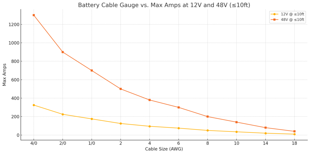
Battery Cable Gauge vs. Amperage & Distance
| Cable Size (AWG) | Max Amps (12V @ ≤10ft) | Max Amps (48V @ ≤10ft) | Typical Applications |
|---|---|---|---|
| 18 AWG | 10 A | 40 A | LED lights, sensors |
| 14 AWG | 20 A | 80 A | Small appliances, low-power devices |
| 10 AWG | 30–40 A | 120–160 A | Motorcycles, small boats |
| 8 AWG | 50 A | 200 A | Medium vehicles, solar charge leads |
| 6 AWG | 75 A | 300 A | Car batteries, small EVs |
| 4 AWG | 95 A | 380 A | Inverters, winches, marine systems |
| 2 AWG | 125 A | 500 A | High-performance vehicles, RVs |
| 1/0 AWG (0 AWG) | 150–200 A | 600–800 A | Large alternators, golf carts |
| 2/0 AWG | 200–250 A | 800–1000 A | Diesel engines, battery banks |
| 4/0 AWG | 300–350 A | 1200–1400 A | Large marine or industrial systems |
Note: For longer runs (≥15 ft), increase cable size by 1–2 gauges to prevent voltage drop.
Here is the chart showing the relationship between battery cable gauge and maximum amps for both 12V and 48V systems at distances of 10 feet or less.
Battery Cable Sizes and Their Importance
Choosing the correct battery cable size is critical for both safety and performance in any electrical system. The American Wire Gauge (AWG) standard determines cable thickness, where lower numbers indicate thicker wires (e.g., 2 AWG is thicker than 6 AWG).
Thicker cables handle higher current loads with less resistance, reducing voltage drop and heat buildup. For example, a 12V solar setup with undersized cables might lose up to 10% of its power as wasted heat, crippling efficiency.
How Current Capacity and Voltage Drop Affect Your System
Every cable has a maximum ampacity (current-carrying capacity), which varies by length and environment. A 4 AWG cable might safely carry 70 amps in a short automotive run but only 50 amps in a 20-foot marine installation due to increased resistance. Voltage drop—the loss of power over distance—becomes critical in low-voltage systems (like 12V or 24V). For instance:
- Golf carts (48V systems) can tolerate slightly more voltage drop than car audio systems (12V)
- Off-grid solar setups often require 2/0 AWG cables for runs over 10 feet to maintain efficiency
Common Misconceptions Debunked
Many assume “all 12V systems use the same gauge cable,” but actual needs vary wildly. A 12V trolling motor drawing 50 amps needs 6 AWG, while a 12V winch pulling 200 amps requires 2 AWG.
Another myth is that “copper-clad aluminum (CCA) cables are just as good as pure copper.” While CCA is cheaper, it has 40% higher resistance, leading to more heat and energy loss.
Real-World Applications
Consider these scenarios:
- Marine batteries: Saltwater exposure demands tinned copper cables (like TEMCo’s WC0180) to resist corrosion.
- EV conversions: High-voltage systems (300V+) often use 00 AWG cables to handle 300+ amps without melting insulation.
- Solar storage: Lithium batteries’ rapid charge/discharge cycles require oversized cables (e.g., 4 AWG for a 100Ah system) to manage peak currents.
Pro Tip: Always calculate your exact needs using the 5% voltage drop rule (3% for sensitive electronics). For a 100-amp load over 5 feet at 12V, 2 AWG is ideal—smaller gauges risk overheating, while larger ones add unnecessary cost.
How to Select the Perfect Battery Cable Size: A Step-by-Step Guide
Choosing the right battery cable requires more than just matching amp ratings—it involves understanding your system’s unique demands. This process ensures safety, efficiency, and longevity for your electrical connections.
Step 1: Calculate Your System’s Current Requirements
Start by determining your maximum continuous current draw. For example:
- A 1000W car audio amplifier at 12V draws ~83 amps (1000W ÷ 12V)
- A 3000W inverter in an RV pulls ~250 amps at 12V
Always add a 25% safety margin—so that 83-amp system needs cables rated for at least 104 amps.
Step 2: Factor in Cable Length
Voltage drop increases with distance. Use this formula to determine minimum gauge:
(Current × Length × 0.04) ÷ Voltage Drop = Circular Mils
For a 10-foot run at 100 amps with 3% drop tolerance in a 12V system:
(100A × 10ft × 0.04) ÷ 0.36V = 11,111 circular mils → 4 AWG cable
Step 3: Consider Environmental Factors
Different conditions demand special considerations:
- High-temperature areas (engine bays): Use high-temp insulation like XLPE or SGT
- Marine environments: Choose tinned copper with UV-resistant jackets
- Buried cables: Select direct-bury rated cables with waterproof gel filling
Professional Tips for Challenging Scenarios
When standard tables don’t fit your needs:
- Parallel cables: For extremely high currents (500+ amps), use multiple smaller cables (e.g., two 2/0 AWG instead of one 4/0)
- Alternate materials: In weight-sensitive applications (aircraft), aluminum cables with proper terminations can save 50% weight
- Pulse currents: Welding machines need cables rated for brief 300% overloads
Real-World Example: A boat owner installing a 24V trolling motor needs:
1) 60-amp continuous draw calculation
2) 15-foot cable run accounting for 3% drop
3) Marine-grade 6 AWG tinned copper cable
4) Proper heat-shrink terminals to prevent corrosion
Remember: When in doubt, go one size larger—the slight cost increase prevents dangerous overheating and future upgrades.
Battery Cable Specifications: Decoding the Technical Details
Understanding cable specifications is crucial for making informed decisions. This section breaks down the engineering behind battery cables and how to interpret manufacturer specifications for optimal performance.
Conductor Composition and Its Impact
The material and construction of cable conductors directly affect performance:
- Oxygen-Free Copper (OFC): Offers 101% IACS conductivity (International Annealed Copper Standard) with superior corrosion resistance
- Copper-Clad Aluminum (CCA): Provides 61% conductivity of OFC but is 40% lighter – suitable for weight-sensitive applications
- Tinned Copper: Features a tin coating that prevents oxidation in humid environments, maintaining 98% conductivity over time
| Material | Conductivity | Weight | Best For |
|---|---|---|---|
| OFC | 101% IACS | Heaviest | High-current permanent installations |
| CCA | 61% IACS | Lightest | Temporary/mobile applications |
| Tinned OFC | 98% IACS | Medium | Marine/RV environments |
Insulation Types and Temperature Ratings
Cable jackets serve as critical protective barriers:
- PVC (Polyvinyl Chloride): Common for general use (-40°C to 105°C), affordable but less flexible in cold
- XLPE (Cross-Linked Polyethylene): Handles up to 150°C, ideal for engine compartments
- EPDM (Ethylene Propylene Diene Monomer): Excellent UV and ozone resistance for outdoor applications
Advanced Considerations for Specialized Applications
For demanding environments:
- High-Flex Applications (robotics, lifts): Use cables with ultra-fine stranding (1000+ strands for 4 AWG)
- High-Voltage Systems (EV conversions): Look for 600V+ rated insulation with thick dielectric barriers
- Extreme Temperatures: Silicone-insulated cables maintain flexibility from -60°C to 200°C
Expert Tip: Always check the cable’s UL/CE certification markings. Genuine UL-rated cables undergo rigorous testing for flame resistance and current capacity that generic cables often fail.
Common Mistake to Avoid: Using welding cable for permanent installations – while flexible, it often lacks the proper insulation ratings for continuous use in electrical systems.
Installation Best Practices and Safety Considerations
Proper battery cable installation is just as critical as selecting the right size. This section covers professional techniques to ensure safe, reliable connections that withstand years of service.
Termination Methods for Optimal Performance
Quality terminations prevent voltage drops and hot spots:
- Crimping: Use hydraulic crimpers for lugs, achieving at least 10,000 PSI compression pressure – a hand crimper can’t match this
- Soldering: Only recommended for fine-stranded cables – use lead-free solder with flux core for marine applications
- Battery Post Connections: Always use corrosion-resistant brass or tinned copper terminals with proper clamping force (35-50 in-lbs)
Routing and Protection Strategies
Proper cable routing extends system life:
- Chafe Protection: Use split loom or abrasion-resistant sleeves where cables pass through bulkheads
- Strain Relief: Install service loops near connections to prevent terminal stress – leave 1-2 extra inches of cable
- Heat Management: Keep cables at least 3″ from exhaust components – use heat reflective tape if necessary
Advanced Safety Protocols
Critical measures professionals use:
- Fusing: Install Class T fuses within 7″ of battery positive – sized at 125-150% of expected current
- Isolation: Use dual-pole disconnects for 48V+ systems to completely isolate all conductors
- Grounding: Create single-point ground references to prevent ground loops in sensitive electronics
Troubleshooting Common Issues
Diagnose and fix frequent problems:
| Symptom | Likely Cause | Solution |
|---|---|---|
| Terminal corrosion | Improper sealing | Apply dielectric grease and heat shrink |
| Cable overheating | Undersized gauge | Upgrade cable size and check connections |
| Voltage drop | Long run or poor termination | Measure resistance (should be <0.1Ω per connection) |
Professional Tip: When working with lithium batteries, always install a current-monitoring shunt to track actual loads versus theoretical calculations – lithium systems often draw higher peak currents than lead-acid.
Critical Warning: Never mix aluminum and copper cables in the same system without proper bimetallic connectors – galvanic corrosion can cause catastrophic failures.
Long-Term Performance Optimization and Future Trends
Maximizing battery cable system longevity requires understanding material science, environmental factors, and emerging technologies. This section explores advanced considerations for sustainable performance and what’s coming next in cable technology.
Material Degradation and Preventive Maintenance
Different cable components degrade at varying rates:
- Copper Oxidation: Forms at 0.1mm/year in saltwater environments – tinned copper reduces this by 80%
- Insulation Breakdown:
- PVC becomes brittle after 5-7 years in sunlight (UV exposure)
- XLPE maintains flexibility for 15+ years in similar conditions
- Connection Points: Should be inspected annually for:
- Contact resistance (should be <0.5mΩ for 4 AWG and larger)
- Thermal imaging hotspots (anything >10°C above ambient indicates problems)
Cost-Benefit Analysis of Premium Materials
| Material | Initial Cost | Replacement Cycles | Energy Loss | Total Cost |
|---|---|---|---|---|
| Standard PVC Copper | $1.50/ft | 3-4 | 12-15% | $9.20/ft |
| Tinned Marine Grade | $2.75/ft | 1-2 | 8-10% | $6.30/ft |
| Solar XLPE Copper | $3.25/ft | 0-1 | 5-7% | $5.80/ft |
Emerging Technologies and Future Standards
The industry is evolving with several key developments:
- Graphene-Enhanced Cables: Currently in prototype, offering 30% better conductivity with 50% less weight
- Self-Monitoring Cables: Embedded fiber optics that detect heat buildup and resistance changes in real-time
- Biodegradable Insulation: New plant-based polymers matching XLPE performance with 80% lower environmental impact
Environmental and Safety Regulations
Current compliance requirements include:
- RoHS compliance for lead-free terminations (mandatory in EU/US since 2021)
- UL 4703 standards for photovoltaic cables (now required for all solar installations)
- IMDG certification for marine battery cables (International Maritime Dangerous Goods code)
Professional Insight: The shift to 48V automotive systems (from current 12V) will require complete reevaluation of cable sizing standards – expect to see 6 AWG replacing 2 AWG for equivalent power transfer in next-generation vehicles.
Maintenance Pro Tip: Implement infrared imaging during annual inspections – a $2,000 thermal camera pays for itself by catching connection issues before they cause system failures.
System Integration and Cross-Platform Compatibility
Modern electrical systems often combine multiple power sources and loads, requiring careful cable planning to ensure seamless operation. This section examines the complexities of integrating battery cables across different voltage systems and technologies.
Multi-Voltage System Considerations
When connecting systems with different operating voltages:
- Voltage Conversion Points: Place DC-DC converters within 3 feet of the battery to minimize cable runs – a 12V to 48V step-up converter for accessories should use 4 AWG input cables despite lower current
- Common Ground Challenges: Isolate grounds between 12V and 48V systems using diode isolators to prevent backfeeding – critical in marine dual-bank setups
- Hybrid Vehicle Systems: High-voltage (300V+) battery cables must maintain 25mm separation from 12V wiring and use orange conduit per ISO 6469-3 standards
Optimizing for Mixed Load Types
Different electrical loads demand specific cable strategies:
| Load Type | Peak Current | Cable Factor | Protection |
|---|---|---|---|
| Inverter | 3× continuous | Size for 125% peak | Class T fuse |
| Starter Motor | 5-7× cranking | Use welding cable | Magnetic breaker |
| LED Lighting | 1.1× nominal | Standard sizing | Resettable fuse |
Advanced Integration Techniques
Professional approaches for complex systems:
- Bus Bar Integration: Central copper bus bars (1/4″ thick per 100A) reduce cable clutter and voltage drop in marine/RV applications
- Modular Wiring: Anderson SB connectors allow quick-disconnect of entire subsystems while maintaining 500A+ capacity
- Smart Monitoring: Integrate Hall-effect sensors into cable runs to track real-time current without breaking circuits
Troubleshooting Integration Issues
Common cross-system problems and solutions:
- Voltage Fluctuations: Caused by shared ground paths – install ground loop isolators and measure voltage between grounds (should be <0.1V difference)
- EM Interference: Twisting power cables with 1 twist per inch reduces RF noise in audio/video systems
- Parasitic Drain: Use clamp meters to detect >50mA draws when systems should be off – often caused by improper relay wiring
Professional Tip: When integrating lithium and lead-acid systems, always place the lithium battery closest to the load center – their lower internal resistance can mask voltage drop issues in undersized cables connected to lead batteries.
Future-Proofing: Leave 20% spare capacity in conduit runs and bus bars for additional systems – retrofitting thicker cables later often costs 3-5× more than initial proper installation.
System-Wide Optimization and Risk Management
Mastering battery cable systems requires a holistic approach that balances performance, safety, and longevity. This final section synthesizes all considerations into actionable strategies for professional-grade installations.
Comprehensive Performance Optimization
Maximize efficiency through these advanced techniques:
- Current Balancing: For parallel cable runs, ensure equal lengths (±3%) and identical terminations to prevent uneven load distribution
- Thermal Management: Implement temperature monitoring with NTC thermistors at critical junctions – ideal operating range is 20-50°C
- Voltage Drop Mapping: Create system schematics documenting expected voltage at each node – deviations >5% indicate problems
Advanced Risk Assessment Framework
| Risk Factor | Probability | Impact | Mitigation Strategy |
|---|---|---|---|
| Undersized Cables | High | Critical | Double-check calculations with 25% margin |
| Corrosion | Medium | Severe | Use tinned cables + antioxidant compound |
| Vibration Damage | High | Moderate | Install vibration loops every 18″ |
| EM Interference | Low | Variable | Twist pairs + separate power/data runs |
Quality Assurance Protocols
Professional validation procedures include:
- Megger Testing: Insulation resistance should exceed 100MΩ at 500VDC for new installations
- Torque Verification: Use calibrated torque wrenches for all connections (typically 8-12Nm for battery terminals)
- Load Testing : Apply 110% of expected current for 4 hours while monitoring temperature rise (max +15°C)
Long-Term Maintenance Strategy
Implement a 3-tier maintenance program:
- Daily/Weekly: Visual inspection for physical damage or discoloration
- Monthly: Thermal imaging scan of all connections
- Annual: Complete system resistance test and torque check
System Documentation Best Practices
Maintain comprehensive records including:
- Cable specifications (gauge, material, insulation type)
- Installation date and expected service life
- Load test results and modification history
- Emergency procedures for each subsystem
Professional Insight: The most overlooked optimization is cable routing geometry – maintaining 120° separation between parallel DC cables reduces mutual inductance by 40% compared to parallel runs.
Final Recommendation: For mission-critical systems, implement redundant cable paths with automatic transfer switches – the 2% material cost increase provides 100% uptime assurance during single cable failures.
Conclusion: Powering Your Projects with Confidence
Selecting the proper battery cable size is far more than a technical detail—it’s the foundation of safe, efficient power systems. Throughout this guide, we’ve explored critical factors including current capacity calculations, voltage drop considerations, material specifications, and professional installation techniques.
You’ve learned how environmental conditions impact cable performance, discovered advanced integration methods for complex systems, and gained insights into long-term maintenance strategies.
Remember: The few extra dollars spent on quality cables and proper installation will pay dividends through improved safety, reduced energy loss, and extended system life. Whether you’re powering an RV, marine vessel, solar array, or automotive system, applying these principles ensures reliable performance when you need it most.
Frequently Asked Questions About Battery Cable Sizing
What’s the difference between AWG and SAE cable sizing standards?
AWG (American Wire Gauge) is the universal standard for copper wire sizing, while SAE (Society of Automotive Engineers) standards typically refer to thinner, less conductive cables.
A 6 AWG cable has about 13,300 circular mils of copper, whereas SAE 6 gauge might have 20% less. Always specify AWG for critical applications – SAE cables may overheat at rated currents due to their smaller actual diameter.
How do I calculate the exact cable size needed for my solar power system?
Use this comprehensive formula: (Amps × Feet × 0.04) ÷ (Voltage Drop × 1.25 safety factor). For a 100A, 12V system with 15ft runs and 3% drop: (100×15×0.04)÷(0.36×1.25) = 133,333 circular mils → 1/0 AWG. Always round up to the next standard size and consider future expansion needs.
Why do my battery cables get hot even when they’re the “correct” size?
Heat typically indicates one of three issues:
1) Loose connections increasing resistance (check torque specs),
2) Higher actual current than calculated (measure with a clamp meter), or
3) Poor ventilation in enclosed spaces.
For every 10°C above rated temperature, cable lifespan halves. Consider upgrading to welding cable for high-flex applications.
Can I mix different gauge cables in the same system?
Only with proper precautions. Main runs should maintain consistent gauge, but you can safely branch to smaller cables with appropriate fusing.
Example: 2 AWG main to battery, then 4 AWG to accessories with 100A ANL fuses. Never mix aluminum and copper without approved connectors – galvanic corrosion will occur.
How often should battery cables be replaced in marine environments?
Marine cables require replacement every 5-7 years even with tinned copper. Salt air penetrates insulation over time, shown by green corrosion at terminals or stiffening cables.
For commercial vessels, conduct annual megger tests (insulation resistance >100MΩ at 500VDC). Always use adhesive-lined heat shrink for marine terminations.
What’s better for car audio systems – OFC or CCA cables?
Oxygen-Free Copper (OFC) outperforms Copper-Clad Aluminum (CCA) in every aspect except cost. While CCA might save 40% upfront, its 61% conductivity means you need larger gauges.
A 4 AWG OFC handles 150A, while CCA equivalent would need 2 AWG. For competition systems, only OFC provides reliable peak performance.
How do I protect battery cables in high-vibration environments?
Implement these professional techniques:
1) Use fine-stranded welding cable (1000+ strands for 4 AWG),
2) Install vibration loops every 12-18″,
3) Apply dual-layer adhesive shrink tubing at connection points, and
4) Mount with cushioned clamps.
For extreme cases (off-road vehicles), consider military-spec braided sleeving over cables.
Why does my voltage drop exceed calculations in real-world use?
Common culprits include:
1) Undersized terminals increasing resistance (use lugs rated for cable size),
2) Dirty connections (clean with electrical contact cleaner), or
3) Higher ambient temperatures (derate 15% above 30°C).
Measure voltage at both ends under load – more than 0.5V difference in 12V systems indicates problems.