
Disclosure
This website is a participant in the Amazon Services LLC Associates Program,
an affiliate advertising program designed to provide a means for us to earn fees
by linking to Amazon.com and affiliated sites.
Choosing the right battery cable size isn’t just about convenience—it’s a critical safety and performance decision. A battery cable size chart reveals the precise American Wire Gauge (AWG) measurements needed to handle your system’s current without voltage drops or dangerous overheating.
Many assume thicker cables are always better, but overspending on unnecessary gauge sizes wastes money while undersized wires risk meltdowns. Whether you’re upgrading a car audio system, solar setup, or marine battery bank, understanding AWG charts unlocks efficient power transfer and prevents costly electrical failures.
Best Battery Cables for AWG Reference
Temco 2 AWG Battery Cable
Ideal for high-current applications like car audio or solar systems, this pure copper cable offers minimal resistance and superior conductivity. Its oil-resistant PVC jacket ensures durability, while the 2 AWG size handles up to 181 amps—perfect for long runs with minimal voltage drop.
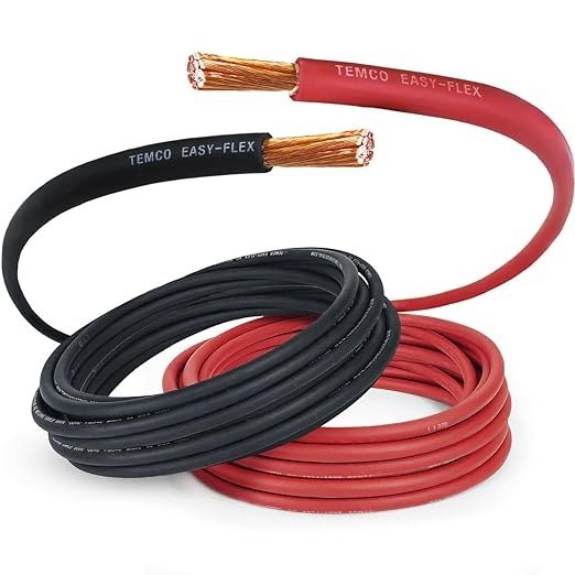
WindyNation 4 AWG Welding/Battery Cable
A versatile, UL-listed option for marine and automotive use, this finely stranded cable bends easily for tight installations. The 4 AWG size supports 135 amps, and its flame-retardant insulation prevents overheating, making it a reliable choice for RVs and power inverters.

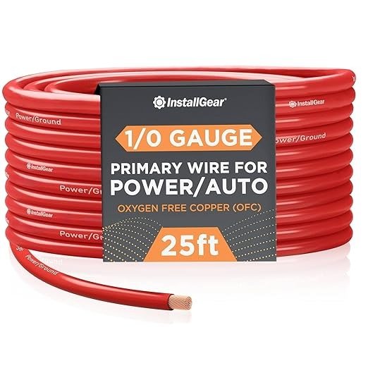
InstallGear 1/0 Guage OFC Battery Cable
Built for extreme power demands, this oxygen-free copper (OFC) cable reduces energy loss in high-performance setups. The 1/0 AWG gauge manages 300+ amps, and its ultra-flexible design simplifies routing in custom car audio or EV conversions without sacrificing current capacity.
AWG and Why Cable Size Matters
The American Wire Gauge (AWG) system is the standard for measuring wire diameters in North America, with a counterintuitive twist – smaller numbers indicate thicker cables. A 4 AWG wire is substantially larger than a 10 AWG wire, for instance.
This numbering system originated in the 19th century based on the number of drawing operations needed to produce the wire, which explains why the scale appears backward to modern users.
How Current Capacity Relates to Wire Gauge
Every wire gauge has a maximum current capacity before overheating occurs. For example:
- 6 AWG handles about 60 amps
- 4 AWG manages approximately 85 amps
- 2 AWG can safely conduct up to 115 amps
These ratings assume copper conductors at 60°C insulation rating – common for most automotive and marine applications. Exceeding these limits risks insulation melting, voltage drops, and potential fire hazards.
The Critical Role of Cable Length
Many DIYers overlook that required wire gauge increases with cable length. A 10-foot 8 AWG cable might work for a car stereo amp, but that same gauge would cause dangerous voltage drops in a 25-foot RV battery run. As a rule of thumb:
- For runs under 10 feet: Use standard AWG charts
- 10-20 feet: Go one gauge size larger
- Over 20 feet: Consult voltage drop calculators
This compensates for resistance buildup over distance, ensuring your starter or inverter receives sufficient voltage.
Material Matters: Copper vs. Aluminum
While copper remains the gold standard for conductivity, some budget cables use aluminum with copper coating. These alternatives:
- Require larger gauges for equivalent current (typically 2 sizes up)
- Are more prone to corrosion at connection points
- May develop hot spots where the coating wears thin
For mission-critical applications like engine starting batteries, pure copper cables (even at higher cost) provide more reliable performance and longer service life.
How to Read and Apply Battery Cable Size Charts
Here is a Battery Cable Size Chart (AWG Reference)
| AWG Size | Max Current (Amps) | Typical Voltage Drop (Volts) | Common Applications |
|---|---|---|---|
| 6 AWG | 105 A | ~2.6 V | Car batteries, small EVs |
| 4 AWG | 125 A | ~2.0 V | Winches, large inverters |
| 2 AWG | 150 A | ~1.6 V | Marine systems, high-performance setups |
| 1/0 AWG | 190 A | ~1.2 V | RVs, solar banks, large audio systems |
| 2/0 AWG | 225 A | ~1.0 V | High-power inverters, diesel engines |
| 4/0 AWG | 300+ A | ~0.8 V | Industrial battery banks, large setups |
Note: Voltage drop varies with cable length and system voltage. Longer runs require thicker cables to maintain efficiency.
Interpreting battery cable size charts correctly is crucial for safe and efficient electrical installations. These charts typically display three key variables: wire gauge (AWG), maximum amperage capacity, and recommended applications. Professional electricians always cross-reference multiple factors when selecting cables, not just the basic amp ratings.
Step-by-Step Chart Interpretation
Follow this professional approach when using AWG charts:
- Determine your system’s peak current draw – Measure with a clamp meter or sum all connected devices’ amperage ratings
- Add a 25% safety buffer – This accounts for startup surges and prevents overheating during continuous loads
- Measure your required cable length – Include all routing paths, not just straight-line distances
- Check temperature ratings – Engine compartments need 105°C+ rated cables versus 60°C for indoor use
For example, a 1000W car audio amplifier drawing 83 amps would need 4 AWG cable (rated 85A) plus 25% buffer = 106A, requiring upgrade to 2 AWG (115A).
Common Installation Challenges and Solutions
Real-world applications often present complications that charts don’t address:
- Tight bends – Use fine-strand cables that maintain flexibility without breaking internal wires
- Multiple parallel runs – When space prohibits large single cables, two smaller gauge wires can share the load (two 8 AWG = one 5 AWG capacity)
- Mixed environments – Marine applications may require tinned copper cables despite higher cost for saltwater corrosion resistance
Professional installers recommend always choosing the next larger gauge when in doubt – the minimal cost increase provides valuable safety margin.
Voltage Drop Calculations in Practice
The formula: Voltage Drop = (2 × Length × Current × Resistance) ÷ 1000 explains why longer runs need thicker cables. For a 15-foot 12V run powering a 50A winch:
- 4 AWG: 0.25Ω/1000ft → 0.375V drop (3.1% of 12V)
- 2 AWG: 0.156Ω/1000ft → 0.234V drop (1.95%)
While both work, the 2 AWG maintains better voltage for consistent winch performance, demonstrating how charts provide minimums while real-world needs often demand upgrades.
Advanced Considerations for Specialized Applications
Beyond basic AWG sizing, professional installations require understanding how environmental factors and unique electrical demands impact cable selection. These advanced considerations separate adequate installations from optimal ones.
Temperature Derating Factors
All wire ratings assume room temperature (30°C/86°F). For every 10°C increase in ambient temperature, current capacity decreases by about 15%. This table shows critical adjustment factors:
| Environment | Typical Temperature | Capacity Adjustment |
|---|---|---|
| Engine Compartment | 70°C (158°F) | Reduce rating by 30-40% |
| Solar Array (rooftop) | 50°C (122°F) | Reduce rating by 15-20% |
| Marine Bilge Area | 40°C (104°F) | Reduce rating by 10-15% |
For example, a 4 AWG cable rated 85A at 30°C would only safely handle about 60A in an engine compartment. This explains why professional automotive wiring often uses oversized cables.
Pulse Current vs Continuous Current
Many applications involve intermittent high-current pulses rather than steady loads:
- Starter motors may draw 300A for 2-3 seconds
- Audio amplifiers have dynamic power demands
- Winches operate in short bursts
For these cases, cables can temporarily handle 2-3 times their continuous rating. However, the National Electric Code (NEC) requires sizing for the highest potential current, not just average draw.
Multi-Conductor Configurations
When running multiple cables in parallel:
- Maintain identical lengths to prevent current imbalance
- Use identical gauge and material for all parallel runs
- Separate cables by at least one cable diameter to prevent heat buildup
- Multiply individual cable ratings by 0.8 (derating factor) for parallel groups
This approach is common in high-performance audio systems where four 4 AWG cables might replace a single 0000 AWG cable for better routing flexibility.
These advanced techniques demonstrate why professional installations often exceed minimum code requirements – they account for real-world variables that basic charts don’t address.
Installation Best Practices and Safety Protocols
Proper cable installation is just as critical as correct gauge selection. Even the highest-quality cables can fail if installed improperly. These professional techniques ensure reliable, long-lasting connections while maintaining safety standards.
Termination and Connection Methods
Secure terminations prevent resistance buildup at connection points:
- Crimping – Use hydraulic crimpers for gauges 4 AWG and larger, ensuring full compression without damaging strands
- Soldering – Only recommended for fine-strand cables after crimping, using rosin-core solder for copper
- Terminal selection – Marine-grade tinned copper lugs outperform standard brass for corrosion resistance
Always apply dielectric grease to finished connections – this prevents oxidation while maintaining conductivity, especially in humid environments.
Routing and Protection Techniques
Cable longevity depends on proper physical installation:
- Use grommets when passing through metal panels to prevent insulation wear
- Maintain bend radius of at least 5x cable diameter to avoid internal damage
- Secure every 18 inches with UV-resistant cable ties or cushioned clamps
- Separate power cables from signal wires by at least 12 inches to prevent interference
In marine applications, use dedicated cable trays and avoid running near fuel lines or moving mechanical parts.
Testing and Verification Procedures
After installation, conduct these essential checks:
- Voltage drop test – Measure under maximum load (should be less than 3% of system voltage)
- Infrared scan – Check for hot spots indicating poor connections
- Continuity test – Verify complete circuit path with multimeter
- Insulation test – Use megohmmeter to detect compromised insulation (minimum 1MΩ resistance)
Document all test results – this baseline data helps diagnose future issues and proves compliance with electrical codes.
These protocols follow NEC Article 400 (Flexible Cords and Cables) and ABYC standards for marine installations. Remember that proper installation often takes longer than the actual cable sizing decision, but prevents costly failures down the line.
Long-Term Performance and Emerging Cable Technologies
Selecting battery cables isn’t just about meeting immediate needs – proper consideration of long-term performance factors and emerging technologies can significantly impact system reliability and total cost of ownership.
Material Degradation and Lifespan Considerations
Different cable materials age at varying rates under operational conditions:
| Material Type | Typical Lifespan | Degradation Factors | Maintenance Requirements |
|---|---|---|---|
| Standard Copper (PVC) | 5-8 years | Oxidation, vibration fatigue | Annual inspection, terminal cleaning |
| Tinned Copper (XLPE) | 10-15 years | Mechanical stress | Biennial resistance testing |
| Silver-Plated Copper (PTFE) | 15-20 years | Cost prohibitive for most applications | Minimal beyond visual checks |
Marine environments typically cut these lifespans by 30-40% due to saltwater exposure, justifying the higher initial cost of tinned copper cables.
Smart Cable Monitoring Systems
Emerging technologies are transforming cable maintenance:
- Embedded sensors measure real-time temperature and resistance, alerting to potential failures
- Self-diagnosing cables use conductive inks that change resistance when insulation degrades
- IoT-enabled connections provide historical performance data for predictive maintenance
While currently limited to industrial applications, these technologies are becoming more accessible for automotive and marine use.
Environmental and Safety Innovations
Recent developments address ecological and safety concerns:
- Halogen-free insulation reduces toxic fumes during fires
- Recyclable composite materials maintain performance while being environmentally friendly
- Phase-change materials in cable jackets absorb excess heat during overloads
These innovations often carry 15-20% cost premiums but may become standard as regulations tighten.
The cable industry is moving toward standardized color-coding for different voltage systems and smart labeling with embedded QR codes containing installation data – changes professionals should monitor as they impact future maintenance and upgrades.
System Integration and Cross-Platform Compatibility
Modern electrical systems often combine multiple power sources and components, requiring careful cable selection to ensure seamless integration.
Hybrid System Cable Requirements
When integrating different power systems (e.g., combining lead-acid and lithium batteries), cable sizing must account for:
- Voltage differentials – Mixed 12V/24V systems require proper gauge selection to prevent imbalance
- Charge profile variations – Lithium systems’ rapid charge acceptance demands higher surge capacity cables
- Grounding considerations – Isolated ground systems need separate cable routing to prevent interference
For example, a solar-charged marine system with AGM house batteries and lithium starting batteries would require:
- Separate 2 AWG cables for the lithium starter circuit (high cranking amps)
- 4 AWG cables for the AGM bank (steady current flow)
- Common 1/0 AWG grounding bus bar with isolation diodes
Automated Load Management Integration
Smart electrical systems with automatic load shedding require specialized cable configurations:
- Voltage sensing lines need 16-18 AWG shielded cable run parallel to power cables
- Current shunt connections require precise 4-wire Kelvin measurement cabling
- Communication buses (CAN, NMEA 2000) must maintain 3″ separation from power cables
Professional installers recommend using different colored cable jackets for each system function (red for power, blue for sensing, yellow for communication) to prevent errors during maintenance.
Troubleshooting Integration Issues
Common cross-system problems and their cable-related solutions:
| Problem | Cable-Related Cause | Solution |
|---|---|---|
| Voltage fluctuations | Undersized interconnects | Upgrade gauge and verify all termination points |
| Ground loop interference | Multiple ground paths | Implement single-point grounding |
| Communication errors | EMI from parallel power runs | Re-route with proper separation or add shielding |
Always test integrated systems under maximum combined load before final installation, as individual component testing won’t reveal interaction issues.
Comprehensive System Validation and Performance Optimization
The final phase of any cable installation requires rigorous validation to ensure optimal performance and long-term reliability.
Advanced Performance Benchmarking
Establishing baseline metrics enables future troubleshooting and performance tracking:
| Test Parameter | Measurement Method | Acceptable Range | Optimization Techniques |
|---|---|---|---|
| Voltage Drop Under Load | Dual-meter differential measurement | <3% of system voltage | Increase gauge size or reduce run length |
| Temperature Differential | Infrared thermography | <10°C above ambient | Improve ventilation or derate current |
| Insulation Integrity | 500V Megger test | >1MΩ resistance | Replace damaged sections or add protective conduit |
Document these benchmarks for future reference, noting environmental conditions during testing.
Risk Assessment and Mitigation Strategies
Professional installers evaluate multiple failure scenarios:
- Single-point failure analysis – Identify critical junctions where one failure could disable entire systems
- Load cycling simulation – Test under repeated surge conditions to identify weak points
- Environmental stress testing – Validate performance in extreme temperatures/vibration
For mission-critical applications (medical, marine, or industrial), consider redundant cable runs for essential circuits with automatic transfer switches.
Long-Term Maintenance Protocols
Implement a comprehensive maintenance schedule:
- Quarterly – Visual inspection for corrosion/chafing, torque check on all terminals
- Biannually – Resistance measurements across critical connections
- Annually – Full thermal imaging scan under maximum load
- Every 3 years – Complete dielectric strength testing
Maintain a detailed service log including ambient conditions during each inspection – this data reveals degradation patterns and predicts remaining service life.
These validation processes ensure your cable installation meets not just immediate needs but delivers reliable performance throughout its entire service life while maintaining safety margins.
Conclusion: Mastering Battery Cable Selection for Optimal Performance
Understanding battery cable sizing through AWG charts is fundamental to building safe, efficient electrical systems. We’ve explored how proper gauge selection impacts current capacity, voltage drop, and long-term reliability across automotive, marine, and renewable energy applications.
Remember that quality materials, precise installation techniques, and regular maintenance are equally crucial as selecting the correct wire size. As electrical systems grow more complex with hybrid configurations and smart technologies, your knowledge of cable fundamentals becomes increasingly valuable.
For your next project, consult the AWG chart carefully, account for environmental factors, and don’t hesitate to oversize cables slightly for future expansion – your electrical system’s performance and safety depend on these critical decisions.
Frequently Asked Questions About Battery Cable Size Charts and AWG Reference
What exactly does AWG measure in battery cables?
AWG (American Wire Gauge) measures the cross-sectional area of conductive wire, not just its diameter. The gauge number relates to the number of dies the wire was drawn through during manufacturing – lower numbers indicate thicker wires.
For example, 4 AWG cable has a diameter of 0.2043 inches (5.189 mm) with approximately 21,150 circular mils area, while 2 AWG measures 0.2576 inches (6.543 mm) with 33,630 circular mils. This measurement directly affects current capacity and resistance.
How do I calculate the exact cable size needed for my application?
Use this professional calculation method:
1) Determine maximum current draw in amps,
2) Measure total cable run length (positive + negative paths),
3) Select gauge using both ampacity charts (for current) and voltage drop calculators (for length).
For a 100A load with 15-foot total run at 12V: minimum 4 AWG for ampacity (85A), but requires 2 AWG to keep voltage drop under 3%. Always round up to the next available gauge size.
Why do my battery cables get hot even when using the recommended AWG size?
Heat typically indicates one of these issues:
1) Loose or corroded connections increasing resistance,
2) Actual current exceeding rated capacity (check for hidden loads),
3) Multiple cables bundled too tightly preventing heat dissipation, or
4) Insulation rated for lower temperatures than your environment.
For automotive applications, engine heat can derate cable capacity by 25-30% – consider using higher temperature rated insulation.
Can I mix different AWG sizes in the same electrical system?
While possible, mixing gauges requires careful planning. Main power runs should maintain consistent gauge, while smaller branches can reduce size ONLY if properly fused for their capacity.
Never mix gauges in parallel configurations – this causes uneven current distribution leading to overheating. For example, you might use 1/0 AWG for main battery cables but branch to 4 AWG for auxiliary circuits, with appropriate fuses at each reduction point.
What’s the real difference between welding cable and standard battery cable?
Welding cable (like WindyNation’s WND4GA) offers finer strand counts (typically 30% more strands) for extreme flexibility, making it ideal for tight spaces or vibrating environments.
Standard battery cable uses thicker strands for slightly better current capacity per dollar. Welding cable’s EPDM or neoprene jacket also typically provides better oil/chemical resistance than standard PVC battery cable insulation.
How often should battery cables be replaced in automotive applications?
Inspect annually and replace every 5-7 years for standard copper/PVC cables in passenger vehicles. Heavy-duty or harsh environment applications (marine, off-road) may need replacement every 3-4 years.
Key replacement indicators include: visible corrosion (green copper oxide), stiff/inflexible sections, cracked insulation, or more than 0.5V drop across cables under load. Premium tinned copper cables can last 2-3 times longer in corrosive environments.
Is it worth paying extra for oxygen-free copper (OFC) battery cables?
OFC (like SkyHigh’s SH-C0GA) provides measurable benefits for high-performance applications:
1) 1-2% better conductivity than standard copper,
2) Less resistance increase over time, and
3) Better fatigue resistance in vibrating environments.
For everyday vehicles or short cable runs, standard copper suffices. However, for competition audio systems, EVs, or runs over 20 feet, OFC’s superior performance justifies the 20-30% cost premium.
What safety certifications should I look for in quality battery cables?
Prioritize cables with:
1) UL/CSA listing (verifies ampacity ratings),
2) SAE J1127 standard for automotive use,
3) ABYC certification for marine applications, and
4) RoHS compliance for environmental safety.
These ensure proper materials, construction, and testing. Beware of uncertified cables claiming inflated ampacity – authentic 4 AWG cable should handle 85A continuous (105°C rating), not the 150A some discount brands advertise.