
Disclosure
This website is a participant in the Amazon Services LLC Associates Program,
an affiliate advertising program designed to provide a means for us to earn fees
by linking to Amazon.com and affiliated sites.
The voltages across components directly relate to the battery voltage, but the connection depends on circuit configuration.
Many assume all components share the same voltage, but reality is more nuanced. Series and parallel circuits distribute voltage differently, affecting performance.
Best Multimeters for Measuring Voltage in Circuits
Fluke 117 Electrician’s Multimeter
The Fluke 117 is a top-tier multimeter with True-RMS accuracy, making it ideal for measuring voltage drops across components. Its low-input impedance prevents ghost voltage readings, ensuring precise measurements in both series and parallel circuits.

Klein Tools MM720 Auto-Ranging Multimeter
Klein Tools’ MM720 offers a high 1000V CAT IV safety rating, perfect for testing battery and component voltages safely. Its large backlit display and rugged design make it reliable for both beginners and professionals.

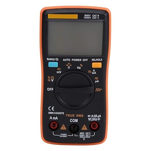
ANENG AN8008 True-RMS Digital Multimeter
For budget-conscious users, the AN8008 delivers True-RMS accuracy and fast sampling rates. It measures AC/DC voltage efficiently, helping you analyze voltage distribution across resistors, capacitors, and other components with confidence.
Voltage Distribution in Series Circuits
In a series circuit, components are connected end-to-end, creating a single path for current flow. The battery voltage gets divided among all components based on their resistance.
This phenomenon follows Kirchhoff’s Voltage Law (KVL), which states that the sum of all voltage drops equals the source voltage.
How Voltage Divides in Series
Each resistor in a series circuit “consumes” part of the battery’s voltage proportional to its resistance. For example, in a 12V circuit with three equal resistors (4Ω each), each resistor drops 4V. This happens because current remains constant in series, while voltage divides according to Ohm’s Law (V = I × R).
- Key Insight: Higher resistance = Larger voltage drop
- Practical Example: Christmas lights often fail in series—if one bulb burns out, the entire string goes dark because the circuit breaks.
Common Misconceptions
Many assume voltage is “used up” by components, but energy is actually converted (e.g., to heat or light). A multimeter placed across each resistor in series will show decreasing voltages, but their sum always matches the battery voltage.
Real-World Application: Voltage Dividers
Engineers use series resistance to create voltage dividers—a fundamental circuit for sensors and adjustable power supplies. For instance, a potentiometer divides voltage by sliding a contact along a resistive track, enabling precise voltage adjustments.
Pro Tip: Always verify voltage drops with a multimeter. If measurements don’t add up to the source voltage, check for faulty connections or unintended parallel paths.
Voltage Relationships in Parallel Circuits
Unlike series circuits, parallel connections create multiple current paths while maintaining equal voltage across all components. This fundamental difference dramatically affects how battery voltage interacts with circuit elements.
The Parallel Circuit Voltage Principle
In parallel configurations, each component receives the full battery voltage regardless of its resistance. This occurs because all branches connect directly to the power source’s positive and negative terminals.
For example, in a 9V circuit with three parallel resistors (10Ω, 20Ω, 30Ω), a multimeter will show exactly 9V across each resistor.
- Key Benefit: Components operate independently – if one fails, others continue working
- Technical Reason: Voltage represents potential difference, which remains constant when measured across common connection points
Current Division in Parallel Circuits
While voltage stays constant, current divides inversely with resistance. Using our 9V example:
- The 10Ω resistor draws 0.9A (I=V/R = 9/10)
- The 20Ω resistor draws 0.45A
- The 30Ω resistor draws 0.3A
The total current equals the sum (1.65A), which you can verify at the battery.
Practical Applications and Considerations
Household wiring uses parallel connections so appliances receive standard 120V (or 240V) regardless of what else is operating. However, this creates important safety considerations:
- Overcurrent Risk: More parallel branches increase total current draw, potentially exceeding wire capacity
- Protection Needed: Always use appropriately rated circuit breakers or fuses
Professional Tip: When troubleshooting parallel circuits, measure voltage first – if it’s correct but a component isn’t working, the issue is likely a broken connection in that specific branch rather than a power supply problem.
Mixed Series-Parallel Circuits: Complex Voltage Relationships
Real-world circuits often combine series and parallel configurations, creating unique voltage distribution patterns. Understanding these hybrid systems is crucial for accurate circuit analysis and design.
Analyzing Voltage Distribution in Combined Circuits
In mixed circuits, you must analyze sections separately before combining results. Follow this methodology:
- Identify parallel sections and calculate their equivalent resistance
- Reduce the circuit to a simple series configuration
- Calculate total current using the simplified circuit
- Work backwards to determine individual component voltages
| Component Type | Voltage Behavior | Current Behavior |
|---|---|---|
| Series Elements | Voltage divides proportionally | Current remains constant |
| Parallel Elements | Voltage remains equal | Current divides inversely with resistance |
Practical Example: Automotive Lighting System
A car’s headlight circuit typically shows this complexity:
- Headlights connect in parallel (each receives full battery voltage)
- Dimmer switch resistors are in series with the parallel headlights
- The series resistor creates a voltage drop, reducing brightness
This explains why both headlights dim equally when using the dimmer function.
Common Mistakes and Solutions
Engineers often encounter these challenges:
- Misidentifying configurations: Always trace current paths completely before analysis
- Ground reference errors: Remember voltage is always measured between two points
- Overlooking power ratings: Mixed circuits can create unexpected power dissipation in certain components
Advanced Tip: Use nodal analysis for complex circuits – this systematic approach calculates voltages at all connection points, then determines component voltages through subtraction.
Voltage Measurement Techniques and Practical Considerations
Accurate voltage measurement across components requires proper methodology and awareness of common pitfalls. Professional electricians and engineers follow specific protocols to ensure reliable results.
Best Practices for Voltage Measurement
When measuring component voltages relative to battery voltage:
- Use proper meter settings: Select AC or DC voltage mode with appropriate range (auto-ranging preferred)
- Connect in parallel: Place probes across the component without disrupting the circuit
- Establish proper reference: Connect the black lead to circuit ground or battery negative
- Consider loading effects: High-impedance meters (>10MΩ) minimize circuit disturbance
Advanced Measurement Scenarios
Special situations require tailored approaches:
- Pulsing DC circuits: Use meters with True-RMS capability for accurate readings
- High-frequency systems: Account for probe capacitance which can affect measurements above 1MHz
- Floating measurements: Use differential probes when neither side connects to ground
Safety Considerations and Industry Standards
Voltage measurement carries inherent risks that demand attention:
- CAT ratings: Always use meters rated for your application (CAT III for household, CAT IV for utility connections)
- Personal protective equipment: Wear insulated gloves when working above 50V
- Live circuit precautions: Keep one hand behind your back to prevent current across the chest
Professional Insight: For critical measurements, use the “3-point check” method: measure known voltage source, then circuit, then known source again to verify meter accuracy throughout the process.
Voltage Optimization and System Efficiency Considerations
Understanding voltage relationships extends beyond basic circuit analysis to system-wide efficiency optimization. Proper voltage management can significantly impact performance, longevity, and energy consumption.
Voltage Drop Analysis in Power Distribution
Excessive voltage drop in electrical systems leads to multiple operational issues:
- Performance degradation: Motors run hotter and less efficiently at lower voltages
- Equipment lifespan: Undervoltage increases current draw, accelerating component wear
- Energy costs: Just 5% voltage drop can increase energy consumption by 10-15% in some systems
| System Type | Recommended Max Voltage Drop | Typical Consequences of Exceeding |
|---|---|---|
| Residential Wiring | 3% (branch circuits) | Dim lighting, appliance malfunctions |
| Industrial Motors | 5% (at full load) | Overheating, reduced torque |
| Solar PV Systems | 2% (DC side) | Significant power output reduction |
Advanced Voltage Regulation Techniques
Modern systems employ various voltage regulation methods:
- Active voltage regulators: Continuously adjust transformer taps for stable output
- Power factor correction: Reduces reactive power and associated voltage drops
- Distributed energy resources: Strategically placed capacitors or battery systems maintain voltage levels
Future Trends in Voltage Management
Emerging technologies are transforming voltage optimization:
- Smart grid systems: Real-time voltage monitoring and automated adjustments
- Solid-state transformers: Enable precise voltage control at distribution level
- AI-powered prediction: Anticipates voltage fluctuations before they occur
Professional Recommendation: Conduct annual voltage profiling across your entire system, measuring at multiple points under various load conditions to identify developing issues before they cause failures or efficiency losses.
Component Selection for Optimal Voltage Performance
Choosing the right components significantly impacts how voltage distributes across a circuit and affects overall system performance.
Key Parameters for Component Selection
When selecting components for voltage-sensitive applications:
- Voltage ratings: Always exceed the maximum expected voltage by at least 25% for safety margin
- Tolerance levels: Precision resistors (±1% or better) maintain predictable voltage division
- Temperature coefficients: Components with low ppm/°C values prevent voltage drift in varying environments
- Power handling: Calculate expected power dissipation (P=V²/R) to prevent overheating
Specialized Components for Voltage Management
Advanced circuits often require specialized components:
- Voltage references: Precision devices like the LM4040 provide stable reference voltages
- Voltage regulators: Switching regulators (e.g., LM2596) efficiently convert higher voltages to lower ones
- Voltage dividers: Optocouplers like the PC817 provide isolated voltage sensing
Practical Design Considerations
Real-world implementation requires additional factors:
- PCB layout: Keep high-impedance voltage divider traces short to prevent noise pickup
- Environmental factors: Humidity and contamination can create parasitic voltage paths
- Long-term drift: Electrolytic capacitors can lose capacitance, affecting RC voltage dividers
Expert Tip: When prototyping, always measure actual component values before installation – a 10% resistor tolerance can create significant voltage variations in precision circuits. Use decade boxes for adjustable voltage division testing.
System-Level Voltage Analysis and Performance Validation
Comprehensive voltage management requires holistic system evaluation that considers all components and their interactions.
Advanced Voltage Mapping Techniques
Professional engineers employ systematic approaches to verify voltage distribution:
- Nodal analysis: Calculate expected voltages at every circuit node using Kirchhoff’s laws
- Thermal imaging: Identify components experiencing abnormal voltage drops through heat patterns
- Transient analysis: Evaluate voltage behavior during startup, shutdown, and load changes
| Validation Method | Measurement Technique | Acceptance Criteria |
|---|---|---|
| Static Verification | DC voltage measurements at all nodes | ±5% of calculated values |
| Dynamic Verification | Oscilloscope capture of transient events | Voltage spikes < 20% of nominal |
| Environmental Testing | Temperature/humidity chamber monitoring | Voltage drift < 2% across operating range |
Comprehensive Risk Mitigation Strategies
Proactive voltage management prevents field failures:
- Derating practices: Operate components at 50-80% of rated voltage for extended lifespan
- Redundant pathways: Parallel components prevent single-point failures in critical voltage nodes
- Condition monitoring: Implement voltage logging for predictive maintenance
Quality Assurance Protocols
Manufacturing validation should include:
- 100% production testing: Automated voltage verification at key test points
- Burn-in testing: 24-72 hour operation at 110% nominal voltage
- Statistical process control: Track voltage parameters across production batches
Engineering Best Practice: Maintain a voltage margin matrix documenting all components’ minimum/maximum operating voltages, including transient conditions. This becomes the foundation for all design reviews and failure analyses.
Conclusion: Mastering Voltage Relationships in Circuits
Understanding how voltages distribute across components is fundamental to circuit design and analysis. We’ve explored the distinct behaviors in series and parallel configurations, along with complex mixed circuits.
The relationship between component voltages and battery voltage follows precise electrical laws. Kirchhoff’s Voltage Law governs series circuits, while parallel connections maintain equal voltage across all branches.
Practical applications range from simple voltage dividers to sophisticated power distribution systems. Proper measurement techniques and component selection ensure accurate voltage management.
Now it’s your turn: Grab a multimeter and experiment with these concepts. Start with basic circuits, then progress to more complex designs. Understanding these voltage relationships will transform your approach to electronics.
Frequently Asked Questions About Voltage Relationships in Circuits
What’s the difference between voltage in series and parallel circuits?
In series circuits, voltage divides across components proportionally to their resistance, with the sum equaling the source voltage. Parallel circuits maintain equal voltage across all branches while current divides. This fundamental difference affects how you design and analyze circuits for different applications.
For example, Christmas lights often use series connections (shared voltage), while home outlets use parallel (full voltage at each device). Understanding this distinction helps prevent circuit design mistakes and ensures proper component selection.
How do I calculate voltage drops across multiple resistors?
First determine total circuit current using Ohm’s Law (I=V/R_total). Then multiply this current by each resistor’s value to find its voltage drop. In series circuits, these drops will sum to your source voltage, verifying your calculations.
For parallel resistors, voltage remains equal across all branches. Use the parallel resistance formula (1/R_total = 1/R1 + 1/R2…) to find equivalent resistance before calculating total current draw from the source.
Why does my circuit show different voltages than calculated?
Common causes include poor connections adding resistance, components operating outside their linear range, or meter loading affecting measurements. Temperature changes can also alter resistance values, particularly in semiconductors and certain resistors.
Always verify your multimeter’s impedance (10MΩ is standard) and check for unintended parallel paths. Even small leakage currents can significantly affect voltage readings in high-impedance circuits.
How does battery voltage affect component selection?
Components must withstand both normal operating voltages and potential spikes. As a rule, select parts rated for at least 1.5 times your maximum expected voltage. Consider transient voltages during switching and temperature-related derating.
For example, a 12V automotive system should use 25V-rated capacitors to handle alternator spikes. Always consult component datasheets for detailed voltage derating curves at different temperatures.
What’s safer: series or parallel connections?
Parallel configurations generally offer safer operation since a single component failure doesn’t disrupt the entire circuit. However, parallel circuits can deliver more current, increasing shock and fire risks if improperly protected.
Always implement appropriate fusing and current limiting. Series connections are safer for high-voltage applications as they naturally limit current, but require careful balancing to prevent overvoltage on individual components.
How do I measure voltage without affecting the circuit?
Use a high-impedance digital multimeter (10MΩ or higher) to minimize loading effects. For sensitive circuits, consider using a buffer amplifier or active probe. Always connect the meter in parallel with the component being measured.
Remember that even 10MΩ impedance can affect high-resistance voltage dividers. In these cases, calculate the meter’s effect or use specialized high-impedance probes (100MΩ+).
Why do my voltage readings fluctuate?
Fluctuations can stem from poor connections, varying loads, or unstable power sources. Switching power supplies may show ripple, while mechanical connections can create intermittent contact resistance.
For diagnosis, first measure the source voltage stability. Then check connections with a continuity tester. If using AC power, consider line voltage variations and whether you’re measuring RMS or peak values.
How does wire gauge affect voltage in a circuit?
Thinner wires have higher resistance, creating larger voltage drops over distance. This becomes critical in high-current applications where even small resistances cause significant power loss (P=I²R).
As a practical example, 16AWG wire drops about 4.1V per 100ft at 10A. Always calculate expected voltage drop (V=IR) when designing long wire runs, especially in low-voltage systems like automotive or solar installations.