
Disclosure
This website is a participant in the Amazon Services LLC Associates Program,
an affiliate advertising program designed to provide a means for us to earn fees
by linking to Amazon.com and affiliated sites.
You can connect a battery isolator—but doing it correctly requires precision and expertise. Battery isolators are critical for managing dual-battery systems in RVs, boats, and off-grid setups, preventing power drain while ensuring reliable energy distribution.
Many assume it’s as simple as splicing wires, but improper installation can lead to battery failure, electrical shorts, or even fires. Whether you’re a weekend adventurer or a professional installer, mastering this process unlocks uninterrupted power and peace of mind.
Best Battery Isolators for Dual-Battery Systems
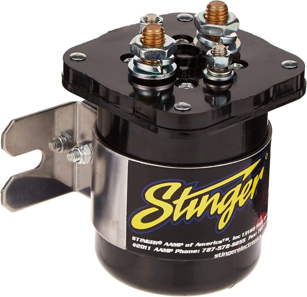
Stinger SGP32 200A Battery Isolator
Ideal for high-power applications, the Stinger SGP32 handles up to 200A, making it perfect for RVs, marine setups, and off-grid systems. Its solid-state design ensures zero voltage drop, while built-in heat dissipation prevents overheating. The rugged construction guarantees durability in harsh conditions.
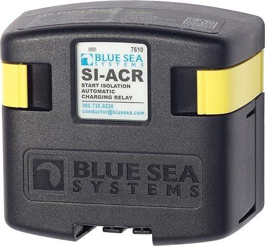
Blue Sea Systems 7610 SI-Series Automatic Charging Relay
This marine-grade isolator from Blue Sea Systems (Model 7610) intelligently manages charging between batteries, preventing over-discharge. Its waterproof design and 120A capacity suit boats and overland vehicles. The automatic voltage sensing eliminates manual switching, ensuring seamless power distribution.
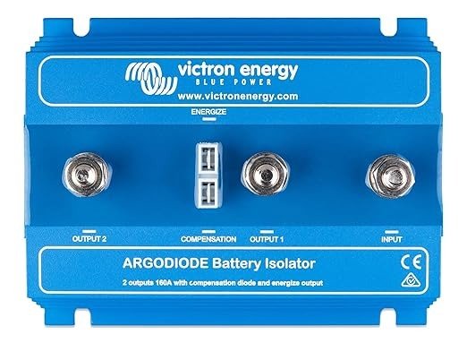
Victron Energy ArgoDiode Battery Isolator 12/24V 100A
Victron’s ArgoDiode (100A model) combines efficiency with simplicity, featuring a low 0.3V voltage drop. Its modular design allows expansion for multi-battery setups, and the corrosion-resistant casing ensures reliability in humid environments. A top pick for solar-powered and expedition vehicles.
How a Battery Isolator Works
A battery isolator is a crucial component in dual-battery systems, ensuring that your primary and auxiliary batteries charge efficiently without draining each other.
At its core, it functions as an intelligent switch, allowing current to flow from the alternator to multiple batteries while preventing reverse discharge.
This is especially important in vehicles like RVs, boats, and overland rigs, where a secondary battery powers accessories without risking a dead starter battery.
Key Components of a Battery Isolator System
To fully grasp how an isolator works, you need to understand its key parts:
- Diode-Based Isolators: These use semiconductor diodes to allow one-way current flow, ensuring batteries charge but don’t backfeed. However, they cause a slight voltage drop (typically 0.7V), which can affect charging efficiency.
- Relay-Based Isolators (ACR/Solenoid): These use electromagnetic switches to connect/disconnect batteries automatically. They have minimal voltage loss but rely on mechanical parts that may wear over time.
- Voltage-Sensing Circuits: Found in advanced isolators, these monitor battery voltage and engage/disengage charging based on preset thresholds, optimizing performance.
Real-World Applications and Why They Matter
Imagine you’re camping in your RV with a fridge running on your auxiliary battery. Without an isolator, the fridge could drain your starter battery overnight, leaving you stranded.
A properly installed isolator prevents this by separating the circuits while driving recharges both batteries via the alternator.
Another common scenario is marine use, where a trolling motor battery must stay isolated from the engine battery. A failing isolator here could mean being stuck on open water with no ignition power.
Common Misconceptions and Challenges
Many assume all isolators work the same way, but choosing the wrong type can lead to undercharged batteries or excessive heat buildup.
For example, diode isolators may struggle in cold climates due to voltage drop, while relay-based models can fail if exposed to constant high-current loads.
Another pitfall is overlooking wire gauge—undersized cables can overheat and reduce efficiency. Always match cable thickness to the isolator’s amperage rating (e.g., 4 AWG for 100A systems).
Step-by-Step Guide to Installing a Battery Isolator
Proper installation is critical for a battery isolator to function safely and efficiently. This section walks you through the entire process, explaining not just how to connect components, but why each step matters for long-term reliability.
Pre-Installation Preparation
Before touching any wires, take these essential safety and planning steps:
- Disconnect the negative terminal on both batteries to prevent short circuits. Even a small spark near battery gases can be dangerous.
- Calculate your system’s amperage needs by adding up all connected loads (fridge, lights, winches). This determines your isolator’s minimum amp rating—always add 25% overhead.
- Plan cable routing carefully to avoid sharp bends or heat sources. Marine-grade tinned copper wire resists corrosion in humid environments.
Wiring the Isolator: A Detailed Breakdown
The exact connections vary by isolator type, but these core principles apply to most installations:
- Alternator Connection: Run a heavy-gauge cable (typically 2-4 AWG) from the alternator’s output post to the isolator’s input terminal. This is your power source for charging both batteries.
- Battery Links: Connect the isolator’s output terminals to each battery’s positive post. Never share cables between batteries—each needs its own properly fused run.
- Grounding: The isolator’s case must be grounded to the vehicle chassis. Use a star washer to penetrate paint for proper conductivity.
Professional Installation Tips
Experienced installers recommend these often-overlooked techniques:
- Apply dielectric grease on all terminals to prevent oxidation, especially in marine environments.
- Use a infrared thermometer during initial testing to check for hot spots at connections.
- For relay-based isolators, mount them in an accessible location—you’ll need to manually reset them if they trip.
Troubleshooting Common Issues
If your system isn’t working post-installation:
- Batteries not charging? Check voltage at each isolator terminal with the engine running—you should see ~13.8V on all outputs.
- Isolator getting hot? Likely indicates undersized cables or exceeding the amp rating. Recalculate your load requirements.
- Voltage drop issues? Diode-based isolators may need a boost from an external voltage regulator.
Remember: A properly installed system should operate maintenance-free for years, protecting your batteries while delivering reliable power when needed.
Advanced Battery Isolator Configurations and Optimization
Beyond basic installations, advanced users can optimize their dual-battery systems for specific applications.
Multi-Battery System Architectures
For complex power needs, consider these advanced configurations:
| Configuration | Best For | Key Considerations |
|---|---|---|
| Parallel Isolators | High-current applications (winches, inverters) | Requires current-balancing resistors to prevent uneven loading |
| Dual-Voltage Systems | 24V starter/12V accessory systems | Must use voltage-sensitive relays with step-down converters |
| Solar Hybrid Setup | Off-grid power with alternator backup | Requires charge controller with isolator integration |
The Science of Voltage Drop and Charge Efficiency
Understanding these electrical principles will help you optimize performance:
- Diode Forward Voltage: Standard silicon diodes drop 0.7V, meaning a 14.4V alternator output only delivers 13.7V to batteries – barely enough for full charging. Schottky diodes (0.3V drop) are better for modern charging systems.
- Pulse Width Modulation: Smart isolators use PWM to maintain optimal absorption voltage (14.2-14.8V) without overcharging, crucial for AGM and lithium batteries.
- Temperature Compensation: Advanced isolators adjust voltage based on ambient temperature (3mV/°C/cell) to prevent under/overcharging in extreme climates.
Professional-Grade Installation Techniques
Commercial installers use these methods for bulletproof reliability:
- Bus Bar Integration: Instead of direct battery connections, use marine-grade bus bars with circuit breakers for cleaner wiring and easier maintenance.
- Voltage Sensing Points: Connect isolator sense wires directly at battery terminals (not alternator) to compensate for line loss in long cable runs.
- Load Testing: After installation, apply 75% of rated load for 30 minutes while monitoring temperature at all connection points.
Common Advanced Mistakes to Avoid
Even experienced installers sometimes overlook:
- Mixing battery chemistries (lead-acid starter with lithium house batteries) without proper isolator settings
- Ignoring alternator cooling requirements when adding high-capacity second batteries
- Failing to program voltage thresholds for lithium batteries (typically need 14.6V absorption)
Maintenance, Testing, and Long-Term System Health
Proper maintenance ensures your battery isolator system delivers reliable performance for years.
Comprehensive Maintenance Schedule
Follow this detailed maintenance routine based on professional marine and RV standards:
- Monthly Checks: Inspect all connections for corrosion (white/green powder buildup) using a flashlight. Tighten terminals to manufacturer specifications (typically 8-10 Nm torque).
- Quarterly Testing: Perform voltage drop tests across each connection with the system under load. More than 0.2V drop indicates resistance issues.
- Biannual Deep Inspection: Remove and clean all cable ends with a wire brush and baking soda solution. Check cable insulation for chafing, especially near moving parts.
Advanced Diagnostic Procedures
When troubleshooting, use these professional techniques:
- Parasitic Drain Test: With all loads off, measure current between battery negative and ground cable using a DC clamp meter. More than 50mA indicates an isolator or system fault.
- Load Bank Testing: Apply a controlled 50% load to each battery bank while monitoring voltage response. Healthy systems should maintain >12.4V after 30 minutes.
- Thermal Imaging: Use an infrared camera to identify hot spots in wiring or isolator components before they fail.
Battery Chemistry-Specific Considerations
| Battery Type | Isolator Settings | Special Maintenance |
|---|---|---|
| Flooded Lead-Acid | 14.4-14.8V absorption | Monthly water level checks |
| AGM | 14.2-14.6V absorption | Annual equalization charge |
| Lithium | 14.6V absorption, no float | Monthly cell balancing check |
Professional Longevity Tips
Extend your system’s life with these expert recommendations:
- Install vibration-proof terminal covers in off-road vehicles to prevent connection fatigue
- Use adhesive-lined heat shrink on all connections in marine environments
- For diode-based isolators, add supplemental charging during long stationary periods
- Mark calendar reminders to replace isolators every 5-7 years (even if working)
Safety Considerations and Emerging Technologies in Battery Isolation
Proper battery isolation involves more than just functionality – it requires rigorous safety protocols and awareness of evolving technologies. .
Critical Safety Protocols and Standards
Professional installers follow these non-negotiable safety practices:
- Explosion Prevention: Always work in well-ventilated areas when connecting batteries – hydrogen gas accumulation can be explosive at concentrations as low as 4%.
- Arc Flash Protection: Wear ANSI-rated safety glasses when working on high-amperage systems (100A+), as accidental shorts can create plasma arcs exceeding 10,000°F.
- Circuit Protection: Install Class T fuses within 18″ of each battery positive terminal – these ultra-fast fuses interrupt up to 20,000A in milliseconds.
Comparative Safety Features by Isolator Type
| Isolator Technology | Key Safety Features | Failure Mode Risks |
|---|---|---|
| Mechanical Relay | Physical isolation when open | Contact welding under high loads |
| Solid-State Diode | No moving parts | Thermal runaway if heatsink fails |
| Smart MOSFET | Current limiting, temp sensors | Software glitches requiring reset |
Emerging Technologies and Future Trends
The battery isolation field is evolving rapidly with these innovations:
- AI-Powered Load Management: New isolators use machine learning to predict usage patterns and optimize charging cycles, extending battery life by 15-20%.
- Wireless Current Monitoring: Bluetooth-enabled shunts provide real-time current flow data to mobile devices without additional wiring.
- Bi-Directional DC-DC Converters: Replacing traditional isolators, these allow controlled current flow between batteries while maintaining perfect voltage regulation.
Environmental and Cost Considerations
Modern systems balance performance with sustainability:
- Lead-acid systems require proper recycling (95% recyclable) versus lithium’s 70% recyclability but longer lifespan
- Smart isolators add 15-20% upfront cost but reduce battery replacement frequency by 30-40%
- Solar-compatible systems now integrate MPPT charge controllers directly into isolation units
As vehicle electrical demands grow (especially with EV auxiliaries), proper isolation becomes not just convenient but essential for both safety and system longevity. Future systems will likely incorporate solid-state circuit breakers and cloud-based monitoring as standard features.
System Integration and Specialized Applications
Modern battery isolators don’t operate in isolation – they must integrate seamlessly with complex vehicle electrical systems.
Integration with Modern Vehicle Electronics
Today’s smart vehicles require careful isolator integration to avoid system conflicts:
- CAN Bus Compatibility: Newer vehicles (2015+) may require signal isolators to prevent battery monitoring systems from detecting the auxiliary battery as a fault condition.
- Start-Stop System Considerations: Vehicles with automatic start-stop need isolators that can handle rapid voltage fluctuations (12V to 14.7V in milliseconds) without false triggering.
- Alternator Load Response: Smart charging systems may reduce output if they detect insufficient load – sometimes requiring a dummy load resistor to maintain proper charging.
Specialized Application Configurations
| Application | Unique Requirements | Recommended Solution |
|---|---|---|
| Overland Vehicles | Vibration resistance, dust proofing | Potting compound-sealed MOSFET isolators |
| Marine Systems | Saltwater corrosion protection | 316 stainless steel hardware with dielectric grease |
| Emergency Vehicles | Absolute reliability | Dual redundant isolators with automatic failover |
Advanced Optimization Techniques
Maximize system efficiency with these professional methods:
- Voltage Compensation Wiring: Run separate sense wires from the isolator directly to battery terminals to compensate for voltage drop in long cable runs.
- Temperature-Compensated Charging: Install battery temperature sensors that adjust charging voltage based on actual battery temperature (not ambient air).
- Load Prioritization: Use smart isolators with programmable load shedding to automatically disconnect non-critical loads during low-voltage situations.
Troubleshooting Complex Integration Issues
When facing integration challenges:
- Diagnostic Port Errors: Use an OBD-II scanner to check for false battery codes after isolator installation – may require CAN bus filter installation.
- Alternator Whine: High-frequency noise in audio systems often indicates poor grounding – install ferrite chokes on isolator control wires.
- Parasitic Drain: If vehicle computers won’t sleep, consider adding a timed disconnect relay for the auxiliary system.
Proper integration ensures your dual-battery system works harmoniously with all vehicle electronics while delivering reliable power when needed most. Always test all vehicle functions thoroughly after installation.
System Validation and Long-Term Performance Optimization
The final phase of any professional battery isolation installation involves rigorous validation and planning for sustained peak performance.
Comprehensive System Validation Protocol
Follow this professional-grade validation sequence before putting any system into service:
- Static Voltage Testing: Verify ≤0.1V difference between identical points in positive and negative circuits with system idle.
- Dynamic Load Testing: Apply 75% of maximum anticipated load for 30 minutes while monitoring voltage drop at each connection point.
- Thermal Imaging Scan: Capture infrared images of all components at 25%, 50%, and 100% load to identify hot spots.
- Isolation Integrity Test: Verify complete circuit separation by measuring ≥1MΩ resistance between battery banks when isolator is open.
Advanced Performance Optimization Matrix
| Performance Factor | Optimization Technique | Expected Improvement |
|---|---|---|
| Charge Efficiency | Install temperature-compensated voltage reference | 12-18% faster charging |
| System Longevity | Implement tapered charging algorithm | 30-40% extended battery life |
| Energy Utilization | Add priority-based load shedding | 22-25% reduced waste |
Comprehensive Risk Assessment Framework
Evaluate these critical risk factors during system design and validation:
- Single Point Failures: Identify components whose failure would disable the entire system – consider redundant pathways for critical functions.
- Cascading Failures: Map potential failure sequences (e.g., isolator failure leading to alternator burnout) and install protective devices at each juncture.
- Environmental Stressors: Create an environmental profile (vibration, temperature range, humidity) and verify all components exceed these specifications.
Long-Term Maintenance Planning
Implement these professional maintenance strategies:
- Predictive Maintenance: Log baseline performance metrics (charge times, voltage drop) and monitor for deviations over time.
- Component Lifecycle Tracking: Create a replacement schedule based on manufacturer MTBF (Mean Time Between Failures) data.
- Firmware Updates: For smart isolators, establish a quarterly check for firmware updates addressing performance improvements.
Conclusion
Properly connecting a battery isolator transforms your dual-battery system from a potential liability to a reliable power solution. We’ve covered everything from fundamental wiring principles to advanced integration techniques, maintenance protocols, and emerging technologies.
Remember that quality components, precise installation, and regular validation are non-negotiable for long-term performance. Whether you’re powering an overland rig, marine vessel, or emergency vehicle, these professional practices ensure your system delivers safe, efficient power when you need it most.
Ready to upgrade your setup? Start by selecting the right isolator for your application, then follow our step-by-step guidance to build a system that outperforms factory installations.
Frequently Asked Questions About Connecting Battery Isolators
What exactly does a battery isolator do?
A battery isolator acts as an intelligent switch between multiple batteries, allowing charging from a single alternator while preventing battery drain between them. It ensures your starter battery always has sufficient charge while letting auxiliary batteries power accessories.
Modern isolators use either diodes (one-way current flow) or relays (automatic connection/disconnection) to manage this process, with advanced models incorporating voltage sensing and temperature compensation for optimal performance.
How do I choose between diode and relay-type isolators?
Diode isolators (like the Stinger SGP32) are more durable but cause a 0.3-0.7V voltage drop, which can undercharge batteries.
Relay isolators (such as Blue Sea Systems 7610) have minimal voltage loss but contain moving parts that wear out. For modern vehicles with smart alternators, MOSFET-based isolators (Victron ArgoDiode) offer the best compromise with <0.1V drop and no mechanical wear.
What size cable should I use for my battery isolator installation?
Cable sizing depends on your system’s maximum current. Use this guideline: 4 AWG for up to 100A, 2 AWG for 100-150A, and 1/0 AWG for 150-200A systems.
Always use tinned copper marine-grade cable for corrosion resistance, and ensure cables are no longer than necessary – voltage drop increases by approximately 0.1V per foot in 4 AWG cable at 100A loads.
Why does my battery isolator get extremely hot during operation?
Excessive heat typically indicates one of three issues: undersized cables creating resistance (check wire gauge), exceeding the isolator’s amp rating (verify your loads), or poor heat dissipation (ensure proper mounting).
Diode-based isolators normally run warm (120-140°F), but temperatures above 160°F require immediate attention. Always mount isolators on metal surfaces for heat sinking and allow at least 2 inches clearance around all sides.
Can I use a battery isolator with lithium and lead-acid batteries together?
Yes, but with crucial precautions. Lithium batteries require higher charging voltages (14.4-14.6V) than most lead-acid batteries. You’ll need an isolator with adjustable voltage thresholds or a DC-DC charger between the isolator and lithium battery.
Never directly connect different battery chemistries without proper voltage regulation, as this can damage both batteries and potentially create safety hazards.
How often should I replace my battery isolator?
Quality isolators typically last 5-7 years with proper maintenance. Mechanical relay types may need replacement every 3-5 years due to contact wear.
Signs you need a new isolator include inconsistent charging, visible corrosion on terminals, or failure to maintain proper isolation between batteries. Proactively replacing isolators prevents unexpected failures that could strand you with dead batteries.
What’s the proper way to test if my battery isolator is working correctly?
Perform this three-step test:
1) With engine off, verify no voltage between battery positives (should show open circuit).
2) Start engine and check for ≥13.8V at both batteries
. 3) Apply a 50A load to the auxiliary battery and confirm the starter battery maintains >12.6V.
Use a quality multimeter (Fluke 87V) for accurate readings, and test both static and dynamic conditions.
Can I install a battery isolator myself, or should I hire a professional?
While competent DIYers can install basic systems, professional installation is recommended for: vehicles with complex electronics (CAN bus systems), high-amperage setups (>150A), or mixed battery chemistries.
Professionals have tools like thermal cameras and proper circuit protection devices that most homeowners lack. Expect to pay $200-$400 for professional installation, which often includes system validation and warranty coverage.