
Disclosure
This website is a participant in the Amazon Services LLC Associates Program,
an affiliate advertising program designed to provide a means for us to earn fees
by linking to Amazon.com and affiliated sites.
Cranking voltage and battery voltage are different—but understanding why is crucial for diagnosing car troubles. Your battery’s health depends on recognizing these distinctions.
Many assume a fully charged battery guarantees smooth starts. But voltage drops during cranking reveal hidden problems like weak cells or excessive resistance.
Best Multimeters for Testing Cranking and Battery Voltage
Fluke 87V Digital Multimeter
The Fluke 87V is a top-tier multimeter for automotive diagnostics, offering True RMS voltage readings and a min/max recording feature. Its rugged design and precise measurements make it ideal for tracking cranking voltage drops and battery health.

Klein Tools MM450 Auto-Ranging Multimeter
Klein Tools’ MM450 provides reliable voltage testing with auto-ranging and a large backlit display. Its low impedance mode prevents ghost voltage readings, ensuring accurate battery and cranking voltage comparisons under real-world conditions.

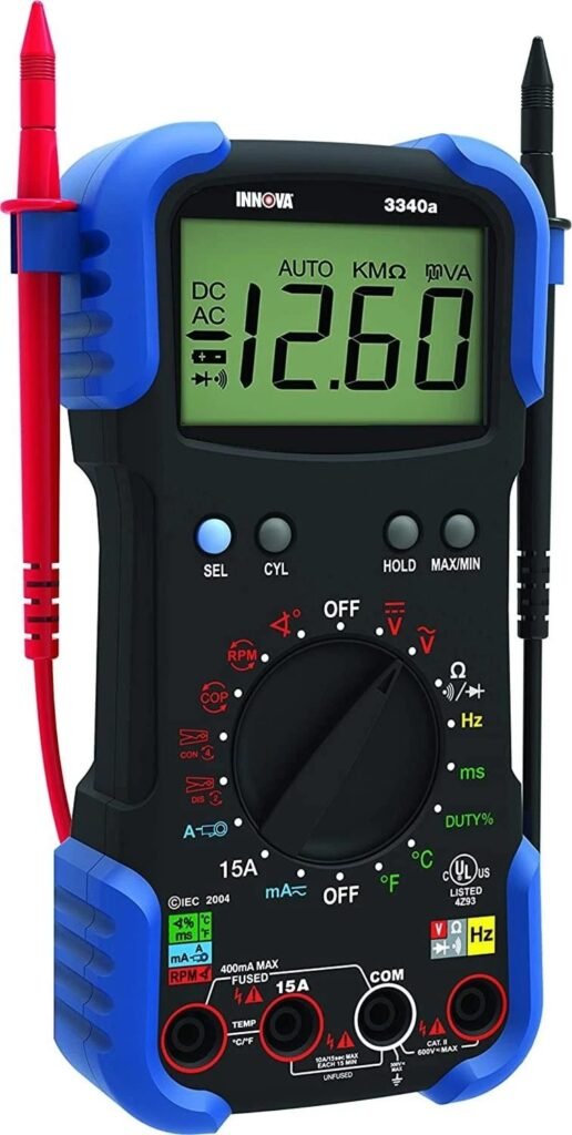
Innova 3340 Automotive Digital Multimeter
Designed for car owners, the Innova 3340 includes dedicated battery test modes and a temperature probe. Its simple interface and durable build help beginners measure cranking voltage safely without complex settings.
Cranking Voltage vs. Battery Voltage: Key Differences
Cranking voltage and battery voltage measure different aspects of your vehicle’s electrical system, yet many confuse them. Battery voltage represents the static charge when the engine is off, typically 12.6V for a healthy battery.
Cranking voltage, however, is the voltage under load when starting the engine, usually dropping to 9.5V–10.5V. This drop occurs because the starter motor demands high current, creating temporary resistance.
Why the Voltage Drop Matters
A significant voltage drop during cranking (below 9V) often indicates underlying issues. Common causes include:
- Weak battery: Sulfation or aging cells reduce capacity
- Poor connections: Corroded terminals increase resistance
- Starter problems: Excessive draw from worn components
For example, a battery showing 12.4V at rest but plunging to 8V during cranking suggests imminent failure, even if it seems charged.
Real-World Testing Scenarios
To diagnose issues accurately:
- Measure resting voltage after the car sits for 12+ hours
- Check cranking voltage during ignition (use min/max mode on multimeters)
- Compare charging voltage (13.7V–14.7V when running)
A 2023 AAA study found 40% of roadside battery failures showed normal resting voltage but critical cranking drops—proof that static tests alone are insufficient.
Technical Insights: The Role of Cold Cranking Amps (CCA)
CCA ratings directly impact cranking performance. A battery with 600 CCA maintains higher voltage under load than a 400 CCA unit in cold weather. This explains why premium batteries often specify both voltage and CCA thresholds for reliable starts.
How to Accurately Measure Cranking and Battery Voltage
Proper voltage testing requires specific techniques to get reliable results. Unlike simple battery checks, cranking voltage measurement captures your electrical system under real operating conditions. Follow this professional-grade procedure to diagnose starting issues correctly.
Step-by-Step Testing Process
- Prepare your multimeter: Set to DC voltage (20V range) and connect red probe to battery positive (+), black to negative (-). For digital models like the Fluke 87V, enable min/max recording.
- Measure resting voltage: With engine off and keys removed, check voltage after 30 minutes. 12.6V indicates full charge; below 12.4V suggests partial discharge.
- Test cranking voltage: Have an assistant crank engine while you observe the voltage drop. Healthy systems maintain 9.5V-10.5V for gasoline engines (diesel may drop to 8V briefly).
Interpreting Your Results
Consider these real-world scenarios:
- Normal reading: 12.6V resting → 10.2V cranking → 14.2V running indicates healthy system
- Battery issue: 12.3V resting → 8.5V cranking suggests weak cells despite “charged” appearance
- Starter problem: Normal resting voltage but cranking voltage below 9V with slow crank points to excessive starter draw
Professional Testing Tips
For most accurate results:
- Test in ambient temperatures above 50°F – cold weather artificially lowers voltage
- Disconnect aftermarket electronics that may create parasitic drain
- Repeat tests after charging suspect batteries to confirm results
Advanced users can perform voltage drop tests across connections by probing between battery terminal and cable end during cranking. More than 0.3V drop indicates resistance needing cleaning or replacement.
Remember that modern vehicles with start-stop systems require specialized testing procedures – consult your service manual for model-specific voltage thresholds.
Advanced Voltage Analysis: Diagnosing Common Starting System Issues
Understanding voltage patterns helps pinpoint specific problems in your starting system. Different voltage behaviors reveal distinct issues that require targeted solutions.
Voltage Pattern Recognition
| Voltage Behavior | Possible Causes | Diagnostic Test |
|---|---|---|
| Slow voltage drop during cranking | Battery sulfation, low electrolyte | Specific gravity test (if applicable) |
| Instant voltage collapse | Bad cell connection, internal short | Load test with carbon pile tester |
| Normal voltage but no crank | Starter solenoid failure | Voltage drop test at starter circuit |
The Science Behind Voltage Drops
Ohm’s Law (V=IR) explains cranking voltage behavior. When current (I) increases through starter resistance (R), voltage (V) must drop. A healthy system minimizes this through:
- Low internal resistance: Quality batteries maintain 0.002-0.004 ohms internal resistance
- Clean connections: Each corroded terminal adds 0.1-0.3 ohms resistance
- Proper cable sizing: Undersized cables create excessive voltage drop (0.5V per 100 amps in 4-gauge wire)
Professional Diagnostic Techniques
Advanced mechanics use these methods:
- Parasitic drain test: Measure current draw with all systems off (should be <50mA for modern vehicles)
- Starter current waveform analysis: Using amp clamps to identify worn bushings or armature issues
- Voltage ripple test: Checks alternator diode health (should be <0.5V AC on DC system)
Common Testing Mistakes to Avoid
- Testing immediately after driving: Surface charge gives false high readings – wait 30+ minutes
- Ignoring temperature effects: Voltage drops 0.01V per °F below 80°F
- Overlooking intermittent issues: Use data-logging multimeters for hard-to-find problems
Remember that modern vehicles with smart charging systems may show different voltage patterns – always consult manufacturer specifications for your particular model.
Optimizing Your Electrical System for Reliable Starting Performance
Beyond basic voltage testing, several key factors determine your vehicle’s starting reliability. Understanding these elements helps prevent premature failures and ensures consistent performance in all conditions.
Battery Selection and Maintenance Best Practices
Choosing the right battery involves more than matching group size. Consider these critical factors:
- CCA vs. CA ratings: Cold Cranking Amps (CCA) measures -18°C performance, while Cranking Amps (CA) tests at 0°C. Northern climates need 20-30% higher CCA than manufacturer minimums.
- Reserve capacity: Measured in minutes, this indicates how long the battery can maintain essential systems if the charging system fails. Modern vehicles with start-stop systems require 120+ minutes.
- Maintenance requirements: Flooded batteries need quarterly electrolyte checks, while AGM types require specialized charging but offer better vibration resistance.
Wiring and Connection Upgrades
Voltage drops often originate in the wiring system. These upgrades can dramatically improve performance:
- Cable upgrades: Replace factory 6-gauge cables with 2-gauge welding cable for high-performance applications (reduces voltage drop by 60%)
- Terminal treatments: Apply anti-corrosion gel under and over connections, not just on surfaces
- Grounding points: Add supplemental ground straps between engine block and chassis (minimum 4-gauge)
Advanced Charging System Considerations
Modern alternators present unique challenges:
| System Type | Normal Voltage Range | Special Considerations |
|---|---|---|
| Conventional | 13.8-14.4V | Check belt tension and diode health |
| Smart Charging | 12.8-15.2V | Voltage varies based on load and temperature |
| Start-Stop | 12.4-14.8V | Requires AGM battery and special testing |
For vehicles with regenerative braking systems, always consult service manuals before testing – incorrect procedures can damage sensitive electronics. When in doubt, use a battery maintainer rather than traditional chargers for these advanced systems.
Future-Proofing Your Vehicle’s Electrical System: Emerging Technologies and Long-Term Strategies
As automotive technology evolves, electrical systems are undergoing radical transformations that impact voltage requirements and maintenance approaches.
The Shift to 48V Electrical Architectures
Modern vehicles are transitioning to 48V mild-hybrid systems, which present new considerations:
| Parameter | 12V Systems | 48V Systems |
|---|---|---|
| Cranking Voltage Range | 9.5-10.5V | 36-42V |
| Current Draw | 150-300A | 40-75A |
| Diagnostic Tools | Standard multimeters | CAT III-rated equipment required |
These systems use DC-DC converters to maintain compatibility with 12V accessories, requiring specialized testing procedures that account for voltage conversion efficiency.
Battery Technology Advancements
Emerging battery chemistries offer improved performance but require different maintenance:
- Lithium Iron Phosphate (LiFePO4): 30% lighter than AGM with 3x cycle life, but requires precise voltage regulation (14.2-14.6V charging)
- Solid-State Batteries: Expected in production vehicles by 2028, offering 2x energy density but needing temperature-controlled charging
- Supercapacitor Hybrids: Used in performance vehicles for instantaneous power delivery without voltage sag
Smart Maintenance Strategies
Modern vehicles demand proactive maintenance approaches:
- Predictive monitoring: Use Bluetooth battery monitors (like Victron BMV-712) tracking state-of-health through charge cycles
- Adaptive charging: Smart chargers (NOCO Genius 10) automatically adjust for battery type and temperature
- Corrosion prevention: Annual application of nano-ceramic coatings to terminals prevents resistance buildup
Safety remains paramount when working with high-voltage systems. Always verify system voltage before testing, and use insulated tools rated for the appropriate voltage class.
As vehicles incorporate more autonomous features, proper electrical maintenance becomes critical not just for reliability, but for overall vehicle safety.
Specialized Voltage Testing Scenarios and Advanced Diagnostics
Beyond standard voltage measurements, several specialized testing scenarios provide deeper insights into your vehicle’s electrical health. These advanced techniques help identify subtle issues before they cause failures.
Parasitic Drain Analysis
Modern vehicles with complex electronics often develop hidden power drains. Follow this comprehensive testing protocol:
- Preparation: Disconnect aftermarket accessories and ensure all doors/trunk are closed with interior lights off
- Initial measurement: Connect multimeter in series between negative terminal and cable (10A DC setting)
- Diagnostic process: If drain exceeds 50mA, systematically pull fuses while monitoring current drop
- Module testing: Suspect modules showing >25mA draw may need reprogramming or replacement
Voltage Drop Testing Under Load
This advanced technique isolates resistance in specific circuits:
| Test Location | Acceptable Drop | Common Failure Points |
|---|---|---|
| Battery to starter | <0.3V at 200A | Corroded terminals, undersized cables |
| Ground connections | <0.1V at 200A | Loose engine grounds, painted surfaces |
| Alternator output | <0.5V at full load | Worn brushes, faulty diodes |
Advanced Waveform Analysis
Using oscilloscopes reveals hidden electrical patterns:
- Starter current waveforms: Worn bushings show erratic current spikes during rotation
- Alternator ripple: More than 0.5V AC indicates failing diodes
- Battery impedance: Rising impedance waveforms predict failure before voltage drops occur
For hybrid/electric vehicles, always use isolated measurement systems when probing high-voltage circuits. The Fluke 1587FC insulation multimeter provides safe testing up to 1000V while maintaining CAT III safety ratings.
Remember that many modern vehicles require specific initialization procedures after battery disconnection – always consult service information before testing.
System-Wide Electrical Optimization and Long-Term Reliability Strategies
Achieving peak electrical system performance requires understanding how all components interact. This comprehensive approach ensures maximum reliability and extends component lifespan.
Integrated Voltage Management Framework
Optimal system performance depends on balancing these key parameters:
| Component | Ideal Voltage Range | Impact on System | Maintenance Interval |
|---|---|---|---|
| Battery | 12.4-12.7V (resting) | ±0.1V affects lifespan by 15% | Monthly checks |
| Charging System | 13.8-14.4V (running) | 0.5V variation = 30% efficiency change | Annual load test |
| Starter Circuit | >9.5V during crank | 1V drop = 25% power loss | Bi-annual inspection |
Comprehensive Risk Mitigation
Preventative measures for common failure modes:
- Voltage spike protection: Install transient suppressors (Littelfuse 0ZCH series) on sensitive circuits
- Corrosion prevention: Apply dielectric grease to all connections and use marine-grade tinned copper cables
- Thermal management: Add heat shielding to starter cables in high-temperature engine bays
Performance Validation Protocol
Implement this quarterly testing regimen:
- Baseline measurement: Record resting, cranking, and charging voltages at 25°C ambient
- Load testing: Verify battery capacity with carbon pile tester (maintain >9.6V at 50% CCA rating)
- Circuit analysis: Perform voltage drop tests on all critical power and ground paths
- Trend analysis: Compare results with previous tests to identify degradation patterns
For mission-critical vehicles (emergency, commercial), consider implementing continuous monitoring systems like the Midtronics CPX-900 with cloud-based analytics.
These systems provide real-time alerts for voltage anomalies and predict failures before they occur. Always maintain detailed service records, as voltage patterns over time often reveal underlying issues before single measurements show problems.
Conclusion
Understanding the relationship between cranking voltage and battery voltage is essential for maintaining your vehicle’s reliability. We’ve explored how these measurements differ, why they matter, and how to test them accurately.
From basic multimeter checks to advanced diagnostic techniques, you now have the knowledge to identify electrical issues before they leave you stranded. Remember that voltage drops during cranking reveal more about your system’s health than static battery tests alone.
Proper maintenance goes beyond simple voltage checks. Implement the comprehensive testing protocols and optimization strategies covered to ensure peak performance in all conditions.
Take action today by performing a complete voltage analysis on your vehicle. Regular monitoring and proactive care will extend your electrical system’s lifespan and prevent unexpected failures. Your vehicle’s starting reliability depends on it.
Frequently Asked Questions About Cranking Voltage and Battery Voltage
What’s the difference between cranking voltage and battery voltage?
Battery voltage measures resting charge (typically 12.6V when fully charged). Cranking voltage shows performance under load during engine start, normally dropping to 9.5-10.5V. This temporary drop occurs because the starter motor draws 150-300 amps, creating resistance in the system.
A healthy system recovers quickly after cranking. If voltage stays below 9V during start or takes more than 2 seconds to recover, you likely have battery, starter, or connection issues needing attention.
How often should I test my vehicle’s cranking voltage?
Test cranking voltage every 3-6 months or before extreme weather seasons. Modern batteries often fail without warning, so regular testing prevents surprises. Include it in routine maintenance checks if your vehicle is over 3 years old or shows starting hesitation.
For high-mileage vehicles or those with start-stop systems, monthly testing is ideal. These systems experience more frequent deep cycles that accelerate battery wear and voltage drop issues.
Why does my battery show 12.6V but won’t start the car?
This common scenario indicates surface charge masking underlying problems. The battery may show proper voltage at rest but collapse under load due to sulfated plates or internal shorts. Always perform both static and cranking voltage tests for accurate diagnosis.
Other causes include corroded terminals adding resistance or a failing starter drawing excessive current. A voltage drop test across connections will identify if resistance is the culprit.
Can cold weather affect cranking voltage readings?
Temperature dramatically impacts voltage performance. For every 15°F below 80°F, available cranking power decreases 20-30%. A battery showing 10V at 70°F might drop to 8V at 0°F, potentially failing to start.
When testing in cold weather, allow for these natural drops. Many quality batteries specify separate Cold Cranking Amp (CCA) ratings precisely for winter performance evaluation.
What’s the safest way to test cranking voltage myself?
Use a digital multimeter with min/max recording (like Fluke 115). Connect to battery terminals before cranking, then have an assistant start the vehicle while you observe. Never disconnect cables during testing as this can damage electronics.
Wear eye protection and ensure the transmission is in Park. Modern vehicles may require special procedures – consult your manual before testing start-stop or hybrid systems.
How much voltage drop is acceptable during cranking?
Gasoline engines should maintain 9.5-10.5V during cranking, while diesels may briefly dip to 8V. Drops below these thresholds indicate problems. The exact specification varies by vehicle – check your manufacturer’s service manual for precise values.
More important than the absolute number is how quickly voltage recovers. Slow recovery (over 2 seconds) suggests battery capacity loss even if the minimum voltage seems acceptable.
Can alternator problems affect cranking voltage?
While the alternator doesn’t directly impact cranking voltage, charging system issues lead to undercharged batteries. A faulty alternator causing chronic undercharging will eventually reduce battery capacity and cranking performance.
Always test charging voltage (13.8-14.4V when running) alongside cranking tests. Intermittent charging can create misleading test results if the battery wasn’t fully charged beforehand.
Are voltage readings different for AGM vs flooded batteries?
AGM batteries typically show slightly higher voltages – 12.8-13.0V when fully charged versus 12.6V for flooded. During cranking, quality AGMs often maintain 0.2-0.3V higher than equivalent flooded batteries.
However, testing procedures remain identical. The key difference is charging – AGMs require specific voltage profiles (usually 14.4-14.8V) that standard chargers may not provide.