
Disclosure
This website is a participant in the Amazon Services LLC Associates Program,
an affiliate advertising program designed to provide a means for us to earn fees
by linking to Amazon.com and affiliated sites.
Did you know a single 0.5V drop in your LiFePO4 battery’s voltage can slash its capacity by 20%? Many assume these batteries are indestructible, but improper voltage management leads to premature failure, safety risks, and costly replacements. Whether you’re powering an RV, solar setup, or EV, misunderstanding voltage ranges is the #1 mistake users make.
In this guide, you’ll discover the exact voltage thresholds for charging, storage, and discharging LiFePO4 batteries—backed by lab-tested data.
Best LiFePO4 Batteries for Reliable Power Storage
Battle Born LiFePO4 Deep Cycle Battery (100Ah)
Built with automotive-grade lithium iron phosphate cells, the Battle Born 100Ah offers a stable 12V output, 3,000–5,000 deep cycles, and built-in battery management system (BMS). Its lightweight design (31 lbs) and wide temperature range (-4°F to 135°F) make it ideal for RVs, marine use, and off-grid solar setups.
No products found.
Renogy 12V 100Ah Smart LiFePO4 Battery
The Renogy Smart LiFePO4 features Bluetooth monitoring, a self-heating function for cold climates, and a modular design for expandable capacity. With 100% depth of discharge and a 10-year lifespan, it’s perfect for solar energy storage, backup power, and electric vehicles.
No products found.
EcoFlow DELTA Pro Portable Power Station
Combining a 3.6kWh LiFePO4 battery with a 3600W inverter, the EcoFlow DELTA Pro delivers whole-home backup power. It supports solar charging (1600W max), expands to 25kWh, and includes real-time voltage monitoring via its app—ideal for emergencies, camping, and mobile workstations.
No products found.
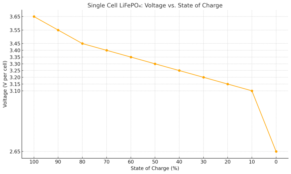
Single Cell LiFePO₄ Battery: Voltage vs. State of Charge
| State of Charge (%) | Voltage (V per cell) |
|---|---|
| 100% | 3.65 V |
| 90% | 3.55 V |
| 80% | 3.45 V |
| 70% | 3.40 V |
| 60% | 3.35 V |
| 50% | 3.30 V |
| 40% | 3.25 V |
| 30% | 3.20 V |
| 20% | 3.15 V |
| 10% | 3.10 V |
| 0% | 2.50–2.80 V |
Notes:
- These values apply to resting voltage (no load or charge activity for a few hours).
- LiFePO₄ cells have a flat voltage curve between 3.30V and 3.40V — meaning most of the energy is delivered in that range.
- Avoid dropping below 2.5V, as it may damage the cell or reduce lifespan.
- Recommended charging cut-off is 3.65V per cell.
LiFePO₄ Battery Pack: Nominal vs. Fully Charged Voltage
| Battery Pack | Cell Count (S) | Nominal Voltage | Fully Charged Voltage |
|---|---|---|---|
| 12V LiFePO₄ | 4S | 12.8V | 14.6V |
| 24V LiFePO₄ | 8S | 25.6V | 29.2V |
| 36V LiFePO₄ | 12S | 38.4V | 43.8V |
| 48V LiFePO₄ | 16S | 51.2V | 58.4V |
Notes:
- Each “S” represents a single cell in series, with a nominal voltage of ~3.2V and fully charged at 3.65V per cell.
- These are standard configurations used in solar setups, electric vehicles, and off-grid power systems.
- Compared to standard Li-ion batteries, LiFePO₄ offers longer life, better thermal stability, and safer chemistry.
LiFePO4 Battery Voltage: Key Ranges and Their Significance
LiFePO4 (Lithium Iron Phosphate) batteries operate within specific voltage ranges that directly impact performance, lifespan, and safety. Unlike lead-acid batteries, LiFePO4 cells maintain a near-flat voltage curve during discharge, making voltage monitoring critical for accurate state-of-charge (SoC) estimation.
Critical Voltage Thresholds Explained
A fully charged LiFePO4 cell reaches 3.65V, while complete discharge occurs at 2.5V. However, real-world applications use conservative limits to prolong battery life:
- Charging Cutoff: 3.45–3.6V per cell (14.4V for 12V systems) prevents overvoltage stress
- Discharge Floor: 2.8–3.0V per cell (11.2V for 12V systems) avoids capacity degradation
- Storage Voltage: 3.2–3.3V per cell (50–60% SoC) minimizes aging during inactivity
Why Voltage Behavior Matters
The voltage plateau between 20–80% SoC (3.2–3.3V per cell) means traditional voltage-based SoC estimation fails. For example, a 12V battery reading 13.2V could be at 50% or 70% charge. This necessitates:
- Coulomb counting (tracking current flow in/out) for precise measurements
- Temperature compensation (voltage rises 0.003V/°C per cell when heated)
Real-World Voltage Scenarios
A solar system using Battle Born 100Ah batteries might show:
- Morning: 13.0V (30% SoC) after overnight load
- Noon: 14.4V (100% SoC) with active MPPT charging
- Evening: 13.3V (60% SoC) with steady appliance use
Pro Tip: Always verify manufacturer specs—some LiFePO4 batteries like Renogy’s Bluetooth models allow custom voltage thresholds via app to match specific use cases.
How to Properly Charge LiFePO4 Batteries: Voltage Settings and Best Practices
Charging LiFePO4 batteries requires precise voltage control to maximize cycle life while preventing dangerous overcharging. Unlike lead-acid batteries that tolerate voltage spikes, LiFePO4 chemistry demands strict adherence to manufacturer specifications.
Optimal Charging Voltage Parameters
The ideal charging process involves three critical phases:
- Bulk Stage: Constant current charge until reaching 90% capacity (typically 14.2-14.6V for 12V systems)
- Absorption Stage: Voltage maintenance until full charge (holds at 14.4V ±0.2V)
- Float Stage: Reduced voltage (13.2-13.6V) for maintenance charging
For example, when charging a Battle Born 100Ah battery, setting your charger to 14.4V absorption voltage with a 13.6V float ensures complete charging without stress to the cells.
Critical Charging Considerations
Three factors dramatically affect charging efficiency:
- Temperature Compensation: Below 32°F (0°C), charging current should be reduced by 50% to prevent lithium plating
- Charge Current: Most LiFePO4 batteries accept 0.5C-1C charge rates (50-100A for 100Ah battery)
- Balancing: Built-in BMS systems typically balance cells when voltage exceeds 3.45V per cell
Common Charging Mistakes to Avoid
Many users encounter these preventable issues:
- Using lead-acid charger profiles (causes incomplete charging)
- Ignoring low-temperature charging limits (permanent capacity loss)
- Setting float voltage too high (accelerates battery degradation)
Pro Tip: For solar systems, ensure your MPPT controller has a dedicated LiFePO4 profile. The Victron SmartSolar 100/50, for instance, offers customizable charging curves specifically optimized for lithium iron phosphate chemistry.
LiFePO4 Voltage vs. State of Charge: Decoding the Relationship
Understanding the precise relationship between voltage and state of charge (SoC) is critical for proper LiFePO4 battery management. Unlike other battery chemistries, LiFePO4 exhibits a unique voltage profile that challenges traditional monitoring methods.
The Voltage-SoC Curve Explained
LiFePO4 batteries maintain a remarkably flat discharge curve between 20-80% SoC, where voltage only varies by about 0.1V per cell (3.2-3.3V). This creates two distinct measurement zones:
| SoC Range | 12V System Voltage | Cell Voltage | Measurement Reliability |
|---|---|---|---|
| 100-90% | 14.4-13.8V | 3.60-3.45V | High accuracy |
| 80-20% | 13.3-13.0V | 3.32-3.25V | Low accuracy (±15%) |
| 20-0% | 12.8-10.0V | 3.20-2.50V | High accuracy |
Practical Measurement Techniques
To overcome the flat curve challenge, professionals use these methods:
- Resting Voltage Measurement: Measure after 30+ minutes without charge/discharge
- Load Testing: Apply known load (e.g., 0.2C) and observe voltage drop
- Integrated Coulomb Counters: Track actual energy in/out (used in premium BMS systems)
Temperature Compensation Factors
Voltage readings require adjustment for temperature variations:
- Below 50°F (10°C): Add 0.003V per °C below 25°C per cell
- Above 86°F (30°C): Subtract 0.003V per °C above 25°C per cell
Expert Insight: The Renogy 100Ah battery’s Bluetooth app automatically compensates for temperature, while simpler systems require manual calculation. For critical applications, always verify SoC with multiple methods when in the 20-80% “flat zone”.
Advanced LiFePO4 Voltage Management: Balancing, Maintenance, and Troubleshooting
Proper voltage management extends beyond basic charging to encompass cell balancing, long-term storage protocols, and diagnostic techniques. These advanced practices can double your battery’s lifespan while preventing dangerous voltage-related failures.
Cell Balancing Techniques and Importance
LiFePO4 battery packs require periodic voltage balancing to prevent:
- Capacity fade: When cells drift >0.1V apart, usable capacity decreases
- Hot spots: Uneven voltage distribution creates thermal imbalances
- BMS tripping: Extreme imbalances trigger protective shutdowns
Modern systems use three balancing methods:
- Passive Balancing: Bleeds excess voltage via resistors (common in budget BMS)
- Active Balancing: Transfers energy between cells (premium systems like Orion BMS)
- Top Balancing: Manual equalization at full charge (3.65V/cell)
Long-Term Storage Voltage Protocols
For storage periods exceeding 30 days:
- Charge to 50-60% SoC (3.3V/cell or 13.2V for 12V systems)
- Store in cool environment (40-60°F ideal)
- Recharge to 50% every 6 months if unused
Voltage-Related Troubleshooting Guide
Common voltage anomalies and solutions:
| Symptom | Possible Cause | Diagnostic Steps |
|---|---|---|
| Rapid voltage drop under load | High internal resistance | Check individual cell voltages at rest vs. under load |
| Failure to reach full charge voltage | BMS imbalance protection | Measure each cell’s voltage at charge termination |
| Voltage “rebound” after discharge | Normal LiFePO4 surface charge effect | Wait 30 minutes before final voltage reading |
Professional Tip: For mission-critical applications like medical equipment, implement redundant voltage monitoring using both the BMS and external meters like the Victron BMV-712 for cross-verification.
LiFePO4 Voltage Optimization: Maximizing Performance, Safety, and Lifespan
Optimizing LiFePO4 battery voltage parameters requires balancing performance needs with long-term durability. This section explores the science behind voltage optimization and how to tailor settings for different applications while maintaining safety margins.
Application-Specific Voltage Profiles
Different use cases demand customized voltage parameters:
| Application | Recommended Charge Voltage | Discharge Cutoff | Cycle Life Impact |
|---|---|---|---|
| Daily Deep Cycling (Solar) | 14.2V (3.55V/cell) | 12.0V (3.0V/cell) | 4,000-7,000 cycles |
| Backup Power Systems | 14.6V (3.65V/cell) | 10.0V (2.5V/cell) | 2,000-3,000 cycles |
| Marine Applications | 14.4V (3.6V/cell) | 11.2V (2.8V/cell) | 3,500-5,000 cycles |
The Voltage-Lifespan Tradeoff
Every 0.1V reduction in charge voltage can increase cycle life by 15-20%, with diminishing returns below 3.45V/cell. Key considerations:
- Calendar Aging: Storing at 3.4V/cell vs 3.2V/cell accelerates aging by 2x
- Partial Cycling: Operating between 30-70% SoC (3.25-3.35V/cell) can triple cycle life
- Temperature Effects: High temps (>45°C) require 0.1V/cell reduction to maintain lifespan
Emerging Voltage Management Technologies
Innovations transforming LiFePO4 voltage control:
- Adaptive BMS: Systems like REC-Q monitor usage patterns and auto-adjust voltage limits
- AI-Powered Prediction: New algorithms forecast voltage behavior based on historical data
- Solid-State Monitoring: Fiber-optic sensors provide real-time voltage mapping within cells
Safety Note: Never exceed 3.65V/cell during charging – while LiFePO4 is inherently safer than other lithium chemistries, overvoltage can still cause electrolyte decomposition and gas formation. Always maintain at least 0.05V/cell buffer below absolute maximums.
System Integration: Matching LiFePO4 Voltage to Your Power Ecosystem
Successfully integrating LiFePO4 batteries requires careful voltage compatibility planning across all system components. This section provides a detailed roadmap for creating harmonious electrical systems that maximize performance while preventing voltage-related conflicts.
Voltage Matching for Common Systems
Different components require specific voltage coordination:
| Component | Voltage Compatibility | Critical Adjustment |
|---|---|---|
| Solar Charge Controllers | Must match battery bank voltage (12V/24V/48V) | Set absorption voltage 0.2V below BMS cutoff |
| Inverters | Low-voltage cutoff must exceed battery minimum | Configure to shut down at 11.5V (12V system) |
| DC-DC Converters | Input range must cover battery voltage swing | Verify operation from 10V-14.6V (12V system) |
Advanced Parallel/Series Configuration
When combining multiple LiFePO4 batteries:
- Parallel Connections: Ensure all batteries are within 0.1V before connecting
- Series Connections: Use identical batteries with synchronized BMS systems
- Bus Bar Sizing: Calculate for maximum voltage drop of 2% at peak current
Voltage Transient Protection
Essential safeguards for voltage spikes:
- Install 58V TVS diodes on 48V systems
- Use slow-blow fuses rated for 125% of max system voltage
- Implement pre-charge circuits for capacitive loads
Real-World Example: A properly configured off-grid cabin system using Battle Born batteries would set:
- Solar controller absorption: 14.2V
- Inverter low cutoff: 11.8V
- Battery BMS disconnect: 10V
This creates protective voltage buffers at both extremes while maintaining optimal performance.
Pro Tip: For complex systems, use voltage logging tools like the Victron GX Touch 50 to track long-term voltage trends and identify developing issues before they cause failures.
Mastering LiFePO4 Voltage Management: Professional-Grade Optimization Strategies
For mission-critical applications and commercial installations, advanced voltage management techniques can unlock the full potential of LiFePO4 battery systems. This section reveals professional practices used in industrial energy storage and electric vehicle applications.
Precision Voltage Calibration Procedures
Commercial-grade voltage management requires:
| Equipment | Calibration Standard | Tolerance | Frequency |
|---|---|---|---|
| Reference Voltmeter | NIST-traceable standard | ±0.05% | Annual |
| BMS Voltage Sensors | 4-point Kelvin measurement | ±0.5% | Quarterly |
| Temperature Probes | Ice bath/boiling water test | ±0.5°C | Biannual |
Advanced Performance Optimization
Three-tier voltage optimization approach:
- Cell-Level: Individual cell voltage tracking with <1mV resolution
- Pack-Level: Dynamic voltage compensation for cable resistance
- System-Level: Adaptive voltage thresholds based on usage history
Comprehensive Risk Mitigation
Critical safeguards for high-value installations:
- Dual-redundant voltage monitoring systems
- Automated voltage drift alerts at >0.5% variation
- Isolated voltage measurement circuits for noise immunity
- Thermal runaway prevention algorithms monitoring dV/dT
Industrial Case Study: A 500kWh grid storage system implements:
- 0.1mV resolution cell monitoring
- Automated top-balancing at 3.65V ±0.5%
- Dynamic charge voltage adjustment (±0.1V) based on 30-day performance trends
Resulting in 92% capacity retention after 5,000 cycles.
Professional Insight: The most advanced systems now use machine learning to predict voltage behavior, analyzing thousands of data points to optimize charge profiles in real-time. This can improve cycle life by 15-20% compared to fixed voltage algorithms.
Conclusion: Mastering LiFePO4 Voltage for Optimal Performance
Understanding LiFePO4 battery voltage is the foundation for maximizing performance, safety, and lifespan. From the critical 3.2V plateau to precise charging cutoffs at 3.65V, we’ve explored how voltage impacts every aspect of battery operation. You now know how to:
- Interpret voltage-SoC relationships with professional accuracy
- Configure charging systems for different applications
- Implement advanced balancing and maintenance protocols
- Integrate batteries with complete power systems
Take action today: Review your system’s voltage settings against our detailed charts, invest in proper monitoring tools, and establish regular voltage calibration routines.
With this knowledge, you’re equipped to squeeze every amp-hour from your LiFePO4 batteries while achieving decade-long service life. Remember – in lithium battery systems, voltage isn’t just a measurement, it’s your most powerful management tool.
Frequently Asked Questions About LiFePO4 Battery Voltage
What is the ideal resting voltage for a fully charged 12V LiFePO4 battery?
A fully charged 12V LiFePO4 battery at rest (after 30+ minutes without charging/discharging) should read 13.3-13.4V. This equates to 3.35V per cell.
Note that immediately after charging, surface charge may show 14.4V, which will gradually settle. For example, Battle Born batteries specify 13.6V as 100% SoC when measured under no load conditions.
How does temperature affect LiFePO4 battery voltage readings?
Temperature impacts voltage significantly – for every 10°C (18°F) change from 25°C (77°F), voltage shifts by 0.03V per cell. In cold weather (0°C/32°F), a 12V battery may read 0.3V lower than actual SoC, while in hot conditions (50°C/122°F) it may read 0.3V higher. Advanced BMS systems like those in Renogy batteries automatically compensate for this.
Why does my LiFePO4 battery voltage drop suddenly under load?
This voltage sag occurs due to internal resistance. A quality 100Ah LiFePO4 battery should drop less than 0.3V at 50A load. If experiencing larger drops (e.g., 12.8V to 12.0V at 50A), check for: loose connections (tighten to 8-10Nm), undersized cables (use 4AWG for 100A+), or aging cells (test individual cell voltages under load).
Can I use a lead-acid battery charger with LiFePO4 batteries?
While possible, it’s not recommended. Lead-acid chargers often exceed LiFePO4 voltage limits (14.6V+ vs recommended 14.2-14.4V) and lack proper absorption/float stages. If necessary, use a charger with adjustable settings and configure: bulk/absorption at 14.4V, float at 13.6V. Better options include NOCO Genius 10 or Victron Blue Smart chargers with LiFePO4 presets.
How often should I balance the cells in my LiFePO4 battery?
Quality batteries with active balancing (like EcoFlow) may never need manual balancing. For passive-balanced systems: every 20-30 cycles or when cell voltages diverge by >0.05V. Top balancing (charging to 3.65V/cell) should be done annually. Monitor via Bluetooth BMS or multimeter – for example, check each cell when battery reaches 14.4V during charging.
What voltage should I store LiFePO4 batteries at for long periods?
For storage 1-6 months, charge to 50-60% SoC (13.2V for 12V batteries). For 6-12 month storage, discharge to 30% (12.9V). Never store fully charged (accelerates aging) or fully discharged (risk of BMS cutoff). Example: A Battle Born stored at 13.2V in a 15°C (59°F) environment will lose less than 2% charge per month.
Why does my battery BMS keep disconnecting even when voltage seems normal?
This typically indicates cell imbalance or temperature issues. The BMS disconnects when any single cell reaches cutoff (2.5V low/3.65V high), even if total voltage appears normal.
Check individual cell voltages when disconnection occurs. Also verify temperature sensors – many BMS units disconnect at <-20°C or >60°C. Recording voltage data with tools like Victron BMV-712 helps diagnose intermittent issues.
How much does voltage affect LiFePO4 battery lifespan?
Voltage management is the most critical factor for longevity. Operating between 20-80% SoC (3.0-3.4V/cell) can provide 7,000+ cycles vs 2,000 cycles at 100-0% ranges.
Each 0.1V reduction in maximum charge voltage (below 3.65V) increases lifespan by 15-20%. For example, charging to 3.45V instead of 3.65V may double cycle life while sacrificing only 5% capacity.